Internet Fiber Channel Protocol (iFCP) deals with the backup and storage of data in a Storage Area Network (SAN). iFCP is a gateway-to-gateway protocol that supports the services of fiber channel fabrics to fiber channel devices in a Transmission Control Protocol/Internet Protocol (TCP/IP) network. A fiber channel fabric is a group of entities in which different N_PORTs are interconnected. N_PORT is a device entity that acts as an interface between the fiber channel devices.
iFCP helps extend fiber channel SANs over the Internet. It enables you to pass data to and from the fiber channel storage devices in a SAN or the Internet using TCP/IP. TCP provides options to control congestion in data flow, check errors, and retrieve data for the fiber channel SANs. iFCP merges the Small Computer System Interface (SCSI) and the fiber channel networks with the Internet. The fiber channel network is an interconnection of fiber channel nodes while SCSI is a protocol to transfer blocks of data in a network. iFCP can replace or be used with the existing fiber channel protocols, such as Fiber Channel over Internet Protocol (FCIP).
This ReferencePoint describes the iFCP concept, architecture, and implementation as well as its advantages and disadvantages. It also discusses its current status and growth potential.
Concept of Fiber Channel
The fiber channel is a frame-based technology designed for peer-to-peer communication at gigabit speeds between fiber channel storage devices. The fiber channel ensures connectivity over several kilometers and supports various data rates, media types, and connectors.
Fiber Channel Network
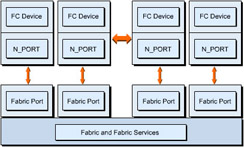
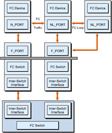
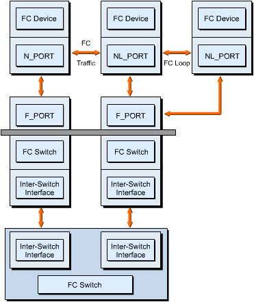
A fiber channel network is a combination of functional components and their interfaces in a fiber channel fabric. It consists of N_PORTS, fiber channel end-devices, fabric ports, a set of auxiliary servers, and network address resolution. Figure 6-1-1 shows a fiber channel network with its components:
Layers of Fiber Channel
A fiber channel protocol has five layers: FC-0, FC-1, FC-2, FC-3, and FC-4. Table 6-1-1 lists these layers:
Topologies of a Fiber Channel Network
A topology is a conceptual arrangement of a network, including its nodes and connecting links. The topologies defined by a fiber channel are:
-
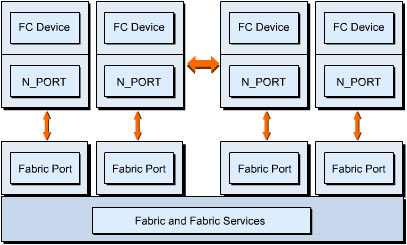
Point-to-Point: Is a connection between two N_PORTs, as shown in Figure 6-1-2. The sharing of media does not take place. It provides a dedicated full bandwidth connection.
-
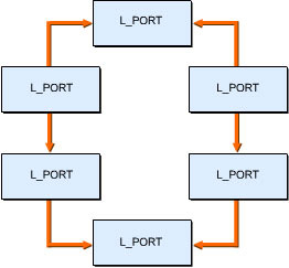
Arbitrated Loop: Is a series of N_PORTs, called L_PORTs, attached to one another in a loop, as shown in Figure 6-1-3. This topology provides connectivity for 127 ports in a network. The accessibility of end-devices is restricted because the media is not shared among them. The end-device used in the loop must be a loop device. Arbitration is required to gain control over the loop to transmit data.
-
Switched Fabric: Interconnects and communicates with many end-devices simultaneously in a fabric topology. This topology does not need to share the media. It is categorized into multi-switch and mixed fiber channel fabric topologies:
-
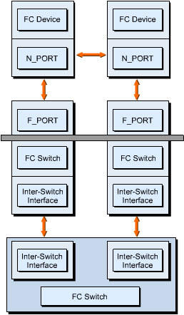
The multi-switch fiber channel fabric topology consists of many switching elements. Figure 6-1-4 shows the multi-switch fiber channel fabric topology:
-
The mixed fiber channel fabric topology is a combination of an arbitrated loop and a switched fabric, as shown in Figure 6-1-5:
-
Format of a Fiber Channel Frame
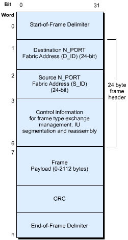
A fiber channel frame is a combination of a header, a payload, and a 32-bit Cyclic Redundancy Check (CRC). CRC checks for errors in a fiber channel frame. The Start of Frame (SOF) and End of Frame (EOF) delimiters are the start and end points of each fiber channel frame. The header contains information related to routing of frames between N_PORTs and the handling of exchanges and sequences. Figure 6-1-6 provides a schematic view of a fiber channel frame format:
This figure shows the frame header components, such as the source and destination N_PORT fabric addresses, control information, frame payload, and CRC.
Transport Services of the Fiber Channel
The fiber channel defines several communication systems called classes of service or transport services. The selection of a transport service depends largely on the type of data being transmitted from one N_PORT to another. The various transport services are:
-
Class 1: A dedicated connection between two N_PORTs. The two N_PORTs use the full bandwidth of the connection without any disturbance from other network traffic. This results in intact data transmission from the source to the destination. A Class 1 service uses only the end-to-end flow control mechanism and provides an acknowledgement for the delivery of data.
-
Class 2: A multiplex connection that uses the end-to-end flow control mechanism and provides an acknowledgement for the delivery of data. It does not require a dedicated connection to be established. A port can send frames to more than one N_PORT and receive frames from them. A Class 2 service uses both buffer-to-buffer and end-to-end flow controls.
-
Class 3: A multiplex connection that does not acknowledge the delivery of data. It is similar to Class 2 except that it uses only the buffer-to-buffer flow control mechanism.
-
Class 4: A connection-oriented service. It is based on a virtual circuit model. This class of service results in intact data transmission from the source to the destination.
-
Class 5: Reserved for future use.
-
Class 6: A reliable multicast service derived from Class1. A multicast service has one sender of data and multiple receivers in a network. A device that needs to send frames to more than one N_PORT at a time sets up a Class 1 dedicated connection with the multicast server within a fiber channel fabric. A multicast server sets up individual dedicated connections between the originating N_PORT and the destination N_PORTs. It then replicates and forwards the frame to all the N_PORTs.
Logon Processes of the Fiber Channel
A logon process enables an N_PORT to set the operating atmosphere required to communicate with the fiber channel fabric, other N_PORTs, and ULP implementations. The various logon operations are:
-
Fabric Login (FLOGI): A process in which a fiber channel node forms a logical connection with a fiber channel fabric. During this process, the N_PORT registers itself on the fiber channel fabric, obtains the fabric parameters, and receives its N_PORT address. This N_PORT address consists of an IP address and a TCP port number.
-
Port Login (PLOGI): A port-to-port process in which initiators form a session with targets. During this process, the N_PORT establishes communication with other N_PORTs.
-
Process Login (PRLOGI): A process-to-process communication that takes place with FC-4 ULPs.
iFCP Architecture
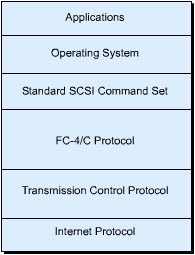
![]() iFCP has a stack of protocol layers in a hierarchical format, as shown in Figure 6-1-7. The advantage of this stack is that it can be incorporated in a Gigabit Ethernet IP network and integrated in a storage controller interface. This results in the integration of fiber channel end-devices and native IP in one IP SAN.
iFCP has a stack of protocol layers in a hierarchical format, as shown in Figure 6-1-7. The advantage of this stack is that it can be incorporated in a Gigabit Ethernet IP network and integrated in a storage controller interface. This results in the integration of fiber channel end-devices and native IP in one IP SAN.
![]() In the iFCP protocol stack, TCP/IP occupies the bottom layer. The FC-4 layer acts as a bridge between TCP/IP and the standard SCSI command set. The protocol stack enables the fiber channel end-device addresses to be mapped to a unique IP address. This provides a native IP addressing system for each fiber channel initiator and target. Initiators are host systems that generate input or output requests. Targets are those storage devices that process the requests generated by the hosts. In the iFCP protocol stack, FC-1, FC-2, and FC-3 are the lower layers of the fiber channel. These layers are replaced with TCP/IP to transmit data through an IP network.
In the iFCP protocol stack, TCP/IP occupies the bottom layer. The FC-4 layer acts as a bridge between TCP/IP and the standard SCSI command set. The protocol stack enables the fiber channel end-device addresses to be mapped to a unique IP address. This provides a native IP addressing system for each fiber channel initiator and target. Initiators are host systems that generate input or output requests. Targets are those storage devices that process the requests generated by the hosts. In the iFCP protocol stack, FC-1, FC-2, and FC-3 are the lower layers of the fiber channel. These layers are replaced with TCP/IP to transmit data through an IP network.
![]() The FC-4 layer defines the upper layer applications that can operate on an IP network and provides a way to utilize the existing protocols without modifying them. The FC-4 mappings are defined for several network protocols. The topmost layer provides a SCSI-3 command set interface for the operating systems and storage applications.
The FC-4 layer defines the upper layer applications that can operate on an IP network and provides a way to utilize the existing protocols without modifying them. The FC-4 mappings are defined for several network protocols. The topmost layer provides a SCSI-3 command set interface for the operating systems and storage applications.
 Network Model of iFCP
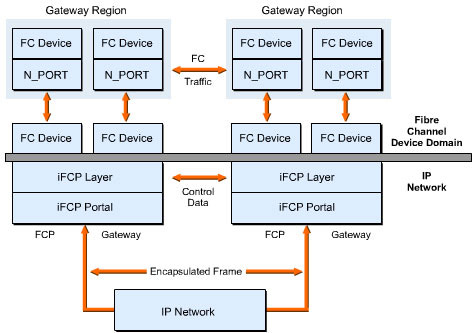
![]() iFCP maps the fiber channel transport services to an IP network, as shown in Figure 6-1-8. In this model, an iFCP gateway connects the existing fiber channel end-devices to an IP network. A gateway is the portion of the fiber channel fabric that acts an interface for another network. Each fiber channel device accesses the network through an N_PORT connected to an interface, such as L_PORT, F_PORT, or FL_PORT. The N_PORT topology can be Point-to-Point, Arbitrated loop, or Switched Fabric. In the fiber channel device domain, other N_PORTs and fiber channel devices internal to a network perform the various fabric services.
iFCP maps the fiber channel transport services to an IP network, as shown in Figure 6-1-8. In this model, an iFCP gateway connects the existing fiber channel end-devices to an IP network. A gateway is the portion of the fiber channel fabric that acts an interface for another network. Each fiber channel device accesses the network through an N_PORT connected to an interface, such as L_PORT, F_PORT, or FL_PORT. The N_PORT topology can be Point-to-Point, Arbitrated loop, or Switched Fabric. In the fiber channel device domain, other N_PORTs and fiber channel devices internal to a network perform the various fabric services.
 Types of iFCP Communications
![]() The types of iFCP communication that take place within a fiber channel frame are:
The types of iFCP communication that take place within a fiber channel frame are:
-
 Device-to-Device: Does not require a supporting fiber channel fabric because data transaction takes place between similar types of devices.
 -
 Device-to-SAN: Requires a supporting fiber channel fabric for data transaction. This fabric maps the data between fiber channel devices and the components of SAN.
 -
 SAN-to-SAN: Uses an existing fiber channel fabric for data transaction. This is possible because iFCP incorporates a TCP/IP network within a SAN.
 Working of iFCP
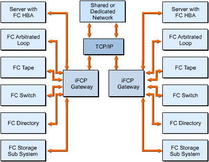
![]() All fiber channel devices, such as fiber channel switches, Host Bus Adapters (HBAs), and tape devices are linked to an iFCP gateway or switch through different paths. A fiber channel switch provides full bandwidth for every port and uses network addressing to route data at a high speed. After reaching the iFCP gateways, the fiber channel sessions end and are transformed into a TCP/IP session through iFCP. Another iFCP gateway or switch receives an iFCP session and starts a fiber channel session in another network. iFCP acts as a facilitator to link sessions between device-to-device, device-to-SAN, and SAN-to-SAN communications. Figure 6-1-9 shows the working of iFCP:
All fiber channel devices, such as fiber channel switches, Host Bus Adapters (HBAs), and tape devices are linked to an iFCP gateway or switch through different paths. A fiber channel switch provides full bandwidth for every port and uses network addressing to route data at a high speed. After reaching the iFCP gateways, the fiber channel sessions end and are transformed into a TCP/IP session through iFCP. Another iFCP gateway or switch receives an iFCP session and starts a fiber channel session in another network. iFCP acts as a facilitator to link sessions between device-to-device, device-to-SAN, and SAN-to-SAN communications. Figure 6-1-9 shows the working of iFCP:
 iFCP Addressing Technique
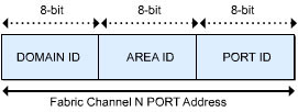
![]() An iFCP design specifies two addressing technique modes to represent a 24-bit fiber channel address of end-devices. The modes are address transparent and address translation. In an address transparent mode, the conventional fiber channel address rules are implemented to assign a unique 24-bit N_PORT addresses. In a standard fiber channel, the fabric switch is obligated to provide a unique N_PORT address during a fabric logon operation. The fiber channel N_PORT address has three 8-bit components: DOMAIN ID, AREA ID, and PORT ID, as shown in Figure 6-1-10:
An iFCP design specifies two addressing technique modes to represent a 24-bit fiber channel address of end-devices. The modes are address transparent and address translation. In an address transparent mode, the conventional fiber channel address rules are implemented to assign a unique 24-bit N_PORT addresses. In a standard fiber channel, the fabric switch is obligated to provide a unique N_PORT address during a fabric logon operation. The fiber channel N_PORT address has three 8-bit components: DOMAIN ID, AREA ID, and PORT ID, as shown in Figure 6-1-10:
![]() Every switch in a standard fiber channel fabric has an assigned DOMAIN ID. There are about 240 unique DOMAIN IDs in a fabric. This determines the theoretical figure of an extended fiber channel network. The AREA ID and PORT ID byte of addressing provides 65,000 blocks of addresses. These addresses can be assigned to individual N_PORTs when they log on to the fiber channel switch. The unification of DOMAIN ID with AREA ID and PORT ID creates a unique 24-bit identity for fiber channel end-devices that are attached to the fabric. DOMAIN ID indicates the switch of the attached device. AREA ID and PORT ID indicate the switch port to which the device is attached.
Every switch in a standard fiber channel fabric has an assigned DOMAIN ID. There are about 240 unique DOMAIN IDs in a fabric. This determines the theoretical figure of an extended fiber channel network. The AREA ID and PORT ID byte of addressing provides 65,000 blocks of addresses. These addresses can be assigned to individual N_PORTs when they log on to the fiber channel switch. The unification of DOMAIN ID with AREA ID and PORT ID creates a unique 24-bit identity for fiber channel end-devices that are attached to the fabric. DOMAIN ID indicates the switch of the attached device. AREA ID and PORT ID indicate the switch port to which the device is attached.
![]() The addressing technique of the fiber channel is dynamic. If a fiber channel end-device is taken off from one switch port and inserted into another port within the same switch, it is assigned a new 24-bit N_PORT address. In this, the DOMAIN ID component does not change as it is still within the same switch but the AREA ID and PORT ID bytes take new values. This process ensures automatic and self-administered addressing within a fiber channel network.
The addressing technique of the fiber channel is dynamic. If a fiber channel end-device is taken off from one switch port and inserted into another port within the same switch, it is assigned a new 24-bit N_PORT address. In this, the DOMAIN ID component does not change as it is still within the same switch but the AREA ID and PORT ID bytes take new values. This process ensures automatic and self-administered addressing within a fiber channel network.
![]() The N_PORT addresses of the fiber channel N_PORT are used in a fiber channel frame header to specify S_ID and D_ID, which are the source and destination addresses, respectively. At the receiving end, the contents of the fiber channel frame are processed at the upper layers of iFCP to check the integrity of the data exchange that is taking place.
The N_PORT addresses of the fiber channel N_PORT are used in a fiber channel frame header to specify S_ID and D_ID, which are the source and destination addresses, respectively. At the receiving end, the contents of the fiber channel frame are processed at the upper layers of iFCP to check the integrity of the data exchange that is taking place.
![]() The address transparent mode accepts the normal fiber channel addressing scheme that enables it to act as a conventional fiber channel fabric. The major drawback of using the standard addressing technique is that every iFCP gateway employs at least one block of 65,000 addresses, even if only a few of them are used for active end-devices. Apart from this, the addressing technique assumes that SAN is one fabric. If more switches or another fabric is added to an existing network, they are assigned new DOMAIN IDs and the attached end-devices are required to log on again to get the new N_PORT addresses. This creates problems for large fiber channel fabrics because they take a long time to return to their normal operative stage.
The address transparent mode accepts the normal fiber channel addressing scheme that enables it to act as a conventional fiber channel fabric. The major drawback of using the standard addressing technique is that every iFCP gateway employs at least one block of 65,000 addresses, even if only a few of them are used for active end-devices. Apart from this, the addressing technique assumes that SAN is one fabric. If more switches or another fabric is added to an existing network, they are assigned new DOMAIN IDs and the attached end-devices are required to log on again to get the new N_PORT addresses. This creates problems for large fiber channel fabrics because they take a long time to return to their normal operative stage.
![]() The address translation mode of iFCP reduces the level of disruption that occurs during data transfer in the address transparent mode. It also enables IP based SANs to scale beyond the fiber channel boundary. In the address translation mode, an iFCP gateway sets 24-bit N_PORT addresses to its locally attached end-devices. The working of this local iFCP gateway is similar to that of a fiber channel switch, except that the local iFCP gateway also assigns N_PORT addresses to remote devices that make them appear as a local resource. If proxy addresses exist, they are used within the boundary of the local iFCP gateway and are not propagated across the IP SAN. The local iFCP gateway itself transfers data between the proxy and actual remote fiber channel addresses. It substitutes the required fiber channel D_ID in the frame header for the proxy D_ID for remote transactions. The address translation mode requires more processing by the local iFCP gateway but avoids the problems posed by fabric-wide addressing. This mode also enables local SANs to get into IP SAN easily.
The address translation mode of iFCP reduces the level of disruption that occurs during data transfer in the address transparent mode. It also enables IP based SANs to scale beyond the fiber channel boundary. In the address translation mode, an iFCP gateway sets 24-bit N_PORT addresses to its locally attached end-devices. The working of this local iFCP gateway is similar to that of a fiber channel switch, except that the local iFCP gateway also assigns N_PORT addresses to remote devices that make them appear as a local resource. If proxy addresses exist, they are used within the boundary of the local iFCP gateway and are not propagated across the IP SAN. The local iFCP gateway itself transfers data between the proxy and actual remote fiber channel addresses. It substitutes the required fiber channel D_ID in the frame header for the proxy D_ID for remote transactions. The address translation mode requires more processing by the local iFCP gateway but avoids the problems posed by fabric-wide addressing. This mode also enables local SANs to get into IP SAN easily.
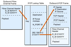
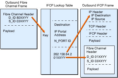
![]() The task of IP address mapping for network traffic is done by the iFCP gateway and is included in the IP frame header. Every iFCP gateway maintains a lookup table to map N_PORT addresses to the corresponding IP addresses, as shown in Figure 6-1-11. If the address translation mode is used, the lookup table includes a mapping of proxy and remote N_PORT addresses.
The task of IP address mapping for network traffic is done by the iFCP gateway and is included in the IP frame header. Every iFCP gateway maintains a lookup table to map N_PORT addresses to the corresponding IP addresses, as shown in Figure 6-1-11. If the address translation mode is used, the lookup table includes a mapping of proxy and remote N_PORT addresses.
![]() In this figure, the domain component "80"of the D_ID address informs the iFCP gateway that this fiber channel frame is intended for a proxy N_PORT address that resides in a remote IP SAN. The iFCP gateway checks for the existence of the address in the iFCP lookup table. This results in two addresses, the actual N_PORT and its associated IP. After building the iFCP frame, the actual N_PORT address is put into the fiber channel frame header and the IP destination one into the IP frame header.
In this figure, the domain component "80"of the D_ID address informs the iFCP gateway that this fiber channel frame is intended for a proxy N_PORT address that resides in a remote IP SAN. The iFCP gateway checks for the existence of the address in the iFCP lookup table. This results in two addresses, the actual N_PORT and its associated IP. After building the iFCP frame, the actual N_PORT address is put into the fiber channel frame header and the IP destination one into the IP frame header.
 iFCP Gateway Processing
![]() iFCP is designed to support the standard fiber channel end-devices and native iFCP devices. The iFCP gateway is a replacement for a fiber channel switch and allows fiber channel N_PORTs to be attached to the gateway. It offers standard fabric services, such as logon operation, SNS registration, and Extended Link Service (ELS). The iFCP gateway also intercepts the fiber channel requests and establishes a TCP/IP connection with the appropriate destination.
iFCP is designed to support the standard fiber channel end-devices and native iFCP devices. The iFCP gateway is a replacement for a fiber channel switch and allows fiber channel N_PORTs to be attached to the gateway. It offers standard fabric services, such as logon operation, SNS registration, and Extended Link Service (ELS). The iFCP gateway also intercepts the fiber channel requests and establishes a TCP/IP connection with the appropriate destination.
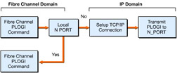
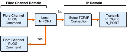
![]() If a locally attached fiber channel end-device sends a PLOGI request to a target, the iFCP gateway determines whether the target is locally attached or is available across the IP SAN, as shown in Figure 6-1-12:
If a locally attached fiber channel end-device sends a PLOGI request to a target, the iFCP gateway determines whether the target is locally attached or is available across the IP SAN, as shown in Figure 6-1-12:
![]() In this figure, a fiber channel PLOGI command is sent to the local N_PORT to check whether the target device is local or not. If it is not a local one, the iFCP gateway sets a TCP/IP connection to the destination. It then transmits PLOGI to the respective N_PORT. If the target device is a local one, the iFCP gateway transmits the fiber PLOGI to the appropriate local N_PORT.
In this figure, a fiber channel PLOGI command is sent to the local N_PORT to check whether the target device is local or not. If it is not a local one, the iFCP gateway sets a TCP/IP connection to the destination. It then transmits PLOGI to the respective N_PORT. If the target device is a local one, the iFCP gateway transmits the fiber PLOGI to the appropriate local N_PORT.
![]() The iFCP gateway intercepts and modifies the maximum data size to less than 1,500 bytes so that the fiber channel frames are easily set in an Ethernet network. Interception is also required for standard fiber channel iSNS queries. The iFCP gateway has an integrated name server function or a combination of internal and external name server resources. An external iSNS server provides name service functions throughout an IP SAN.
The iFCP gateway intercepts and modifies the maximum data size to less than 1,500 bytes so that the fiber channel frames are easily set in an Ethernet network. Interception is also required for standard fiber channel iSNS queries. The iFCP gateway has an integrated name server function or a combination of internal and external name server resources. An external iSNS server provides name service functions throughout an IP SAN.
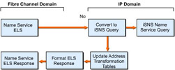
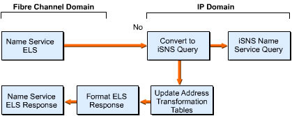
![]() The working of the iSNS server is similar to that of a DNS one of an IP network. When a fiber channel end-device queries a switch iSNS service, it returns a list of fiber channel addresses for available targets. An iFCP gateway internally converts the fiber channel iSNS request into an iSNS query. When the iSNS server responds to the targets, the iFCP gateway records the appropriate fiber channel and IP addresses for its own translation table and formats the iSNS initiator response. This process enables the iFCP gateway to update the address translation tables for further communication between the initiator and the targets, as shown in Figure 6-1-13:
The working of the iSNS server is similar to that of a DNS one of an IP network. When a fiber channel end-device queries a switch iSNS service, it returns a list of fiber channel addresses for available targets. An iFCP gateway internally converts the fiber channel iSNS request into an iSNS query. When the iSNS server responds to the targets, the iFCP gateway records the appropriate fiber channel and IP addresses for its own translation table and formats the iSNS initiator response. This process enables the iFCP gateway to update the address translation tables for further communication between the initiator and the targets, as shown in Figure 6-1-13:
![]() In this figure, an initiator sends a name service ELS request to an iSNS name service query component that converts the request into an iSNS query. This query then updates the address translation tables and formats the ELS response for the initiator.
In this figure, an initiator sends a name service ELS request to an iSNS name service query component that converts the request into an iSNS query. This query then updates the address translation tables and formats the ELS response for the initiator.
 iFCP and TCP/IP Connectivity
![]() An iFCP gateway device appears as a fiber channel switch to its attached fiber channel nodes. An iFCP interface to the IP network does not require fiber channel inter-switch services. Instead, an iFCP gateway forms the TCP/IP connections to other iFCP gateways across the network and uses the IP routing technique to browse the network.
An iFCP gateway device appears as a fiber channel switch to its attached fiber channel nodes. An iFCP interface to the IP network does not require fiber channel inter-switch services. Instead, an iFCP gateway forms the TCP/IP connections to other iFCP gateways across the network and uses the IP routing technique to browse the network.
![]() After the iSNS server recognizes the iFCP gateway and other gateways in the IP network, the iFCP gateway establishes multiple TCP/IP connections amongst themselves. TCP connections are handled by TCP link service messages that are exchanged between the iFCP gateways. TCP/IP connections can be either in a bound or unbound mode. In a bound mode, the active N_PORT traffic passes through the TCP connection. In an unbound mode, the TCP connection is alive but no storage traffic is present. An unbound TCP connection is converted into a bound mode when the iFCP gateway issues a connection bind command to the remote iFCP gateway.
After the iSNS server recognizes the iFCP gateway and other gateways in the IP network, the iFCP gateway establishes multiple TCP/IP connections amongst themselves. TCP connections are handled by TCP link service messages that are exchanged between the iFCP gateways. TCP/IP connections can be either in a bound or unbound mode. In a bound mode, the active N_PORT traffic passes through the TCP connection. In an unbound mode, the TCP connection is alive but no storage traffic is present. An unbound TCP connection is converted into a bound mode when the iFCP gateway issues a connection bind command to the remote iFCP gateway.
![]() Only one fiber channel logon session is allowed for each bound TCP connection. The mapping between the fiber channel and IP addresses and its binding to a dedicated TCP connection ensures that the communication between the fiber channel initiator and the target is on its own dedicated link. When the fiber channel logon session terminates, the TCP connection becomes unbound and is available for other logon sessions.
Only one fiber channel logon session is allowed for each bound TCP connection. The mapping between the fiber channel and IP addresses and its binding to a dedicated TCP connection ensures that the communication between the fiber channel initiator and the target is on its own dedicated link. When the fiber channel logon session terminates, the TCP connection becomes unbound and is available for other logon sessions.
 iFCP Error Handling
![]() iFCP detects errors in the fiber channel and TCP/IP. To do so, iFCP monitors the fiber channel error timeout values, such as error detect timeout value (E_D_TOV) and resource allocation timeout value (R_A_TOV) as well as TCP errors. E_D_TOV and R_A_TOV are timing parameters used to regulate frame transmission and switch resources, respectively. If any fiber channel or TCP related error occurs, only one communicating fiber channel pair gets affected. All the other login sessions remain active.
iFCP detects errors in the fiber channel and TCP/IP. To do so, iFCP monitors the fiber channel error timeout values, such as error detect timeout value (E_D_TOV) and resource allocation timeout value (R_A_TOV) as well as TCP errors. E_D_TOV and R_A_TOV are timing parameters used to regulate frame transmission and switch resources, respectively. If any fiber channel or TCP related error occurs, only one communicating fiber channel pair gets affected. All the other login sessions remain active.
![]() If a particular error in the fiber channel or TCP connection is non-recoverable, the TCP connection supporting the fiber channel logon session is aborted and the related frames are removed. The fiber channel initiator then establishes a fresh logon session to the target network. If the iFCP gateway itself experiences an error related to the IP router or switch, the iFCP gateway terminates all TCP connections and tries to reset the connection to the destination IP SAN.
If a particular error in the fiber channel or TCP connection is non-recoverable, the TCP connection supporting the fiber channel logon session is aborted and the related frames are removed. The fiber channel initiator then establishes a fresh logon session to the target network. If the iFCP gateway itself experiences an error related to the IP router or switch, the iFCP gateway terminates all TCP connections and tries to reset the connection to the destination IP SAN.
iFCP Implementation Issues
![]() The large-scale storage of data over an enterprise-wide IP network or fiber channel SAN necessitates iFCP to be technically viable. For successful implementation of iFCP, some requirements should be met, such as complying with business standards, interoperability with other protocols, better performance, easy management, and the ability to integrate with storage products.
The large-scale storage of data over an enterprise-wide IP network or fiber channel SAN necessitates iFCP to be technically viable. For successful implementation of iFCP, some requirements should be met, such as complying with business standards, interoperability with other protocols, better performance, easy management, and the ability to integrate with storage products.
![]() iFCP provides a high level of scalable implementation using the existing fiber channel storage products. It offers inter-connectivity to multiple fiber channel SANs through TCP/IP networks over any distance by capitalizing the standard Gigabit Ethernet switches and routers. An iFCP environment supports enterprise-wide applications, such as centralized backup, remote mirroring, storage management, and storage virtualization because it can create a scalable fiber channel and IP SAN.
iFCP provides a high level of scalable implementation using the existing fiber channel storage products. It offers inter-connectivity to multiple fiber channel SANs through TCP/IP networks over any distance by capitalizing the standard Gigabit Ethernet switches and routers. An iFCP environment supports enterprise-wide applications, such as centralized backup, remote mirroring, storage management, and storage virtualization because it can create a scalable fiber channel and IP SAN.
| Note | |
 iFCP Device Discovery and Fabric Management
![]() iFCP in a fiber channel fabric should perform the task of device discovery and fabric management using the Internet Storage Name Service (iSNS). Device discovery is the mechanism used by initiators to look for targets in SAN. The components of an iFCP implementation need access to the iSNS server to:
iFCP in a fiber channel fabric should perform the task of device discovery and fabric management using the Internet Storage Name Service (iSNS). Device discovery is the mechanism used by initiators to look for targets in SAN. The components of an iFCP implementation need access to the iSNS server to:
-
 Follow the services provided by the fiber channel name server, such as to notify changes to N_PORT, which occur in the iFCP fabric configuration.
 -
 Synchronize gateways in the iFCP fabric to inter-operate with other networks.
 -
 Create fiber channel zones through definition and management of device discovery scopes.
 -
 Store and issue the security policies.
 iFCP Fabric Properties
![]() A set of iFCP gateways is defined to function as a bounded or unbounded iFCP fabric. A bounded iFCP fabric works in an address transparent mode. The N_PORT address is borrowed from the DOMAIN IDs given by an iSNS server. An unbounded iFCP fabric operates in an address translation mode. The extent of a fiber channel N_PORT address is native or confined to a gateway region.
A set of iFCP gateways is defined to function as a bounded or unbounded iFCP fabric. A bounded iFCP fabric works in an address transparent mode. The N_PORT address is borrowed from the DOMAIN IDs given by an iSNS server. An unbounded iFCP fabric operates in an address translation mode. The extent of a fiber channel N_PORT address is native or confined to a gateway region.
![]() The implementations related to the iFCP gateway must support unbounded iFCP fabrics. There are three concepts that largely determine the implementation of an iFCP fabric: transparency of address being transferred, scalability of implementation, and considerations for a fault tolerant system.
The implementations related to the iFCP gateway must support unbounded iFCP fabrics. There are three concepts that largely determine the implementation of an iFCP fabric: transparency of address being transferred, scalability of implementation, and considerations for a fault tolerant system.
| Note | |
 Operation in Address Translation Mode
![]() The iFCP implementation issues with regard to the address translation mode are:
The iFCP implementation issues with regard to the address translation mode are:
-
 The implementation of all iFCP gateways needs to function in an address translation mode.
 -
 The current mode of operation in an iFCP implementation should not be changed after the fiber channel frame traffic starts its operation.
 -
 The iFCP implementation should not permit operations in more than one mode at a time.
 -
 The iFCP implementation should not create an iFCP session with a gateway that is not in the same mode.
 -
 The iFCP gateway implementation handles the N_PORT address assignment for all the remote end-devices. These remote end-devices are accessed through this iFCP gateway. The iFCP gateway is supposed to allocate a locally significant N_PORT alias to the remote gateway in place of N_PORT ID. This N_PORT ID might be assigned to it by any remote gateway. The assignment of the N_PORT alias is done at the time of device discovery.
 -
 For address conversion and to enable routing, the iFCP gateway forms an iFCP session. It then has to create the information needed to map each N_PORT alias to the suitable TCP/IP connection context and N_PORT ID of an N_PORT that is remotely accessed.
Incompatibility with Address Translation Mode
![]() The implementation issues related to incompatibility with the address translation mode are:
The implementation issues related to incompatibility with the address translation mode are:
-
 While operating in an address transparent mode, the iFCP gateway implementation is not supposed to start or accept frames with a Temporal Reference for Prediction (TRP) bit set to one in the iFCP flags field.
 -
 The iFCP gateway should stop all iFCP sessions with a particular iFCP gateway from which frames are received with the TRP bit set to one.
 Operation in Address Transparent Mode
![]() The iFCP implementation issues with regard to the address transparent mode are:
The iFCP implementation issues with regard to the address transparent mode are:
-
 The iFCP gateways in an address transparent mode should not transact with all those iFCP gateways that do not function in an address transparent mode.
 -
 Each iFCP gateway implementation should handle the DOMAIN_ID assignment according to the fiber channel standards while performing transaction with the locally attached fiber channel switch elements. The iSNS server needs to provide the DOMAIN_ID values assigned to the fiber channel switches that are internal to an iFCP gateway.
 -
 The fiber channel address translation should not occur while working in an address transparent mode.
 -
 The iFCP gateway needs to keep track of all the iFCP session contexts during the operation in an address transparent mode.
Incompatibility with Address Transparent Mode
![]() The implementation issues related to incompatibility with the address transparent mode are:
The implementation issues related to incompatibility with the address transparent mode are:
-
 The iFCP gateway implementation in an address translation mode should not start or accept frames with the TRP bit set to one in the iFCP flags field of encapsulation header.
 -
 The iFCP gateway should stop all iFCP sessions with a particular iFCP gateway from which frames are received with the TRP bit set to one.
 Transparent Mode DOMAIN ID Management
![]() The iFCP implementation issues with regard to DOMAIN ID management in the transport mode are:
The iFCP implementation issues with regard to DOMAIN ID management in the transport mode are:
 Inbound Frame Address Translation
![]() The iFCP implementation issues with regard to inbound frame address translation are:
The iFCP implementation issues with regard to inbound frame address translation are:
-
 If an iFCP frame is received from an IP network, the receiving gateway should check the session descriptor to set the D_ID field with the destination N_PORT ID and S_ID field with assigned N_PORT alias.
 -
 The receiving gateway should consider the contents of the S_ID and D_ID fields to be undefined when received. After replacing the fields with appropriate values, the iFCP gateway should re-compute the CRC value of the fiber channel fabric.
 iFCP Security
![]() Securing transactions in an iFCP implementation is achieved through several methods. In a fiber channel network, the fiber channel hosts, disks, and tape subsystems are physically assembled. For mission-critical storage applications, the Gigabit Ethernet switches used to connect to the iFCP gateways are dedicated for SAN applications and should not be shared for any other purpose. Creating a separate network for IP storage isolates the sensitive storage data in a secure location. This can be treated as the first step towards a secured data environment.
Securing transactions in an iFCP implementation is achieved through several methods. In a fiber channel network, the fiber channel hosts, disks, and tape subsystems are physically assembled. For mission-critical storage applications, the Gigabit Ethernet switches used to connect to the iFCP gateways are dedicated for SAN applications and should not be shared for any other purpose. Creating a separate network for IP storage isolates the sensitive storage data in a secure location. This can be treated as the first step towards a secured data environment.
![]() In an iFCP environment, the segregation of the storage resource is done using discovery domains that allow authorized initiators to discover and establish sessions with specific target devices. The relationships between trusted initiators and targets can be secured using public and private key authentication techniques through the iSNS server and can be implemented within the iFCP gateways.
In an iFCP environment, the segregation of the storage resource is done using discovery domains that allow authorized initiators to discover and establish sessions with specific target devices. The relationships between trusted initiators and targets can be secured using public and private key authentication techniques through the iSNS server and can be implemented within the iFCP gateways.
![]() An iFCP gateway can use the IP Security for authentication and encryption of data. Third-party gigabit-speed firewalls can be incorporated within IP routers or serve as stand-alone units between an iFCP gateway and an IP router interface on the network.
An iFCP gateway can use the IP Security for authentication and encryption of data. Third-party gigabit-speed firewalls can be incorporated within IP routers or serve as stand-alone units between an iFCP gateway and an IP router interface on the network.
Advantages and Disadvantages of iFCP
![]() The implementation of an enterprise-wide network for critical data storage and management was very difficult and costly earlier. iFCP solved the problem using third-party vendors, who developed robust, high-speed and standards-based IP storage devices for an iFCP based network.
The implementation of an enterprise-wide network for critical data storage and management was very difficult and costly earlier. iFCP solved the problem using third-party vendors, who developed robust, high-speed and standards-based IP storage devices for an iFCP based network.
![]() The advantages of iFCP are that it:
The advantages of iFCP are that it:
-
 Leads SANs performance to gigabit level speeds that helps reduce the rate of latency in a traditional data storage environment. This speed helps send and receive an entire frame of data at a time in an IP SAN.
 -
 Leads to enterprise-wide scalability of SAN due to lower cost in the implementation of iFCP based IP SAN.
 -
 Reduces cost by supporting Ethernet and IP management tools.
 -
 Can be integrated with a Gigabit Ethernet based IP storage or a storage controller interface. This helps iFCP support the use of fiber channel end-devices and IP storage devices within one IP SAN.
 -
 Protocol stack is directly implemented in a Gigabit Ethernet environment. This results in the combined use of FC and IP devices in one IP SAN.
 -
 Supports the use of TCP/IP as its transmission layer protocol to transfer data over an IP network. This does not require defining the working of the transmission layer protocol. The features of TCP/IP can be used to enhance the working of iFCP.
 -
 Implicitly supports the native fiber channel and IP storage devices. As a result, you do not need to design and create new devices for the implementation of iFCP. iFCP helps extend fiber channel SANs over the Internet.
 -
 Enables the fiber channel device addresses to be mapped to a unique IP address. This results in native IP addressing for individual fiber channel initiators and targets.
 -
 Architecture helps route the storage data over WAN through standard IP switches and routers. It does not require the creation of any specialized devices and standards for such a data transfer over WAN.
 -
 Removes barriers that existed in a traditional storage network and fiber channel switching for large-scale data storage over a network.
![]() The primary disadvantage of iFCP is that it currently does not support the new Internet Small Computer System Interface (iSCSI) end-devices. In addition, it has an excessively homogenous management system.
The primary disadvantage of iFCP is that it currently does not support the new Internet Small Computer System Interface (iSCSI) end-devices. In addition, it has an excessively homogenous management system.
Prospects of iFCP
![]() iFCP redefines the concept of data migration between dissimilar networks and end-devices that are currently available. If it can support the new iSCSI-based end-devices, it may prove to be the best available protocol to integrate fiber channel based SAN and IP based SAN. This would result in transfer and storage of data in an IP SAN at gigabit speed for greater distances. The integration with IP SAN helps iFCP use the security features available with TCP/IP.
iFCP redefines the concept of data migration between dissimilar networks and end-devices that are currently available. If it can support the new iSCSI-based end-devices, it may prove to be the best available protocol to integrate fiber channel based SAN and IP based SAN. This would result in transfer and storage of data in an IP SAN at gigabit speed for greater distances. The integration with IP SAN helps iFCP use the security features available with TCP/IP.
 Current Status
![]() Among the available fiber channel protocols, only iFCP is designed to support the existing fiber channel and native IP storage devices. iFCP supports the address translation mode to make the storage network design more flexible. The iFCP gateway helps use fiber channel related disk arrays as well as disk controllers meant for a Gigabit Ethernet interface. At present, the iFCP standard does not provide any specification for the use of iSCSI related end-devices. With the support of third-party vendors, it is possible to integrate fiber channels, iFCP, and iSCSI devices and create a multi-protocol IP based SAN.
Among the available fiber channel protocols, only iFCP is designed to support the existing fiber channel and native IP storage devices. iFCP supports the address translation mode to make the storage network design more flexible. The iFCP gateway helps use fiber channel related disk arrays as well as disk controllers meant for a Gigabit Ethernet interface. At present, the iFCP standard does not provide any specification for the use of iSCSI related end-devices. With the support of third-party vendors, it is possible to integrate fiber channels, iFCP, and iSCSI devices and create a multi-protocol IP based SAN.
![]() iFCP works along the lines of the Gigabit Ethernet by functioning in terms of fiber channel standards. This helps iFCP get the required stability in the market. The Gigabit Ethernet has changed a few bottom layers of the fiber channel architecture for more efficient data transfer. Similarly, iFCP works in the address translation mode to provide better adaptability for the IP SAN based storage network.
iFCP works along the lines of the Gigabit Ethernet by functioning in terms of fiber channel standards. This helps iFCP get the required stability in the market. The Gigabit Ethernet has changed a few bottom layers of the fiber channel architecture for more efficient data transfer. Similarly, iFCP works in the address translation mode to provide better adaptability for the IP SAN based storage network.
![]() iFCP provides a ready-to-use interface for various operating systems and storage applications using the SCSI-3 layer protocol. It supports most of the standard specifications of SAN without any changes. iFCP can easily work in a purely IP based network without fiber channel devices.
iFCP provides a ready-to-use interface for various operating systems and storage applications using the SCSI-3 layer protocol. It supports most of the standard specifications of SAN without any changes. iFCP can easily work in a purely IP based network without fiber channel devices.
Future Growth Potential
An iFCP gateway can support fiber channel disk arrays and disk controllers that have a Gigabit Ethernet interface and an iFCP protocol stack. iFCP can be considered as a migration strategy from the present fiber channel SANs to future IP SANs. It can either complement the existing fiber channel fabrics or replace them completely in the near future. iFCP enables you to build an IP SAN fabric and provides the facility to migrate to a mixed fiber channel environment. In addition, you can use iFCP to optimize the fiber channel fabric component and increase the usage of the TCP/IP network. The growth potential for iFCP lies in its support for fiber channel SAN extensions and the global IP SAN solutions.

