Overview
Fibre Channel over Internet Protocol (FCIP) is a gigabit or multi-gigabit networking technology used to implement Storage Area Networks (SANs). This technology was developed by the Internet Engineering Task Force (IETF).
FCIP maintains all fibre channel services and provides options to manage highly complex SAN networks and share data between them. The various FCIP link devices help connect the Gigabit Ethernet and IP infrastructure to establish and administer an IP-based SAN network.
FCIP encapsulates fibre channel packets and transports them through TCP/IP. This encapsulation enables various applications to be supported by FCIP. It also enables various enterprise networks to use their current network infrastructure to connect and expand fibre channel SANs.
This ReferencePoint describes the concept, components, and structure of FCIP and explores the advantages, disadvantages, and future of FCIP. In addition, it explains FCIP security as well as TCP connection parameters used with FCIP.
Overview of FCIP
![]() FCIP provides interconnectivity of fibre channel SANs over TCP/IP networks. This connectivity helps create a unified SAN in a fibre channel fabric. FCIP depends on IP-based network resources to interconnect SANs over Local Area Networks (LANs), Metropolitan Area Networks (MANs), or Wide Area Networks (WANs).
FCIP provides interconnectivity of fibre channel SANs over TCP/IP networks. This connectivity helps create a unified SAN in a fibre channel fabric. FCIP depends on IP-based network resources to interconnect SANs over Local Area Networks (LANs), Metropolitan Area Networks (MANs), or Wide Area Networks (WANs).
![]() FCIP encapsulates fibre channel frames into TCP segments to link fibre channel SANs over WANs. As a result, FCIP requires a very low amount of IP content to function. FCIP provides IP connectivity between fibre channel SANs and not between individual storage devices.
FCIP encapsulates fibre channel frames into TCP segments to link fibre channel SANs over WANs. As a result, FCIP requires a very low amount of IP content to function. FCIP provides IP connectivity between fibre channel SANs and not between individual storage devices.
![]() FCIP also enables the transfer of fibre channel data by tunneling it among one or more SANs across a TCP/IP network. Tunneling is the process of transmitting the confidential data of an enterprise network over a public network. Data is tunneled without the notice of the public network. Tunneling helps data to be shared over a widely distributed enterprise network.
FCIP also enables the transfer of fibre channel data by tunneling it among one or more SANs across a TCP/IP network. Tunneling is the process of transmitting the confidential data of an enterprise network over a public network. Data is tunneled without the notice of the public network. Tunneling helps data to be shared over a widely distributed enterprise network.
![]() The FCIP tunneling protocol uses TCP/IP as the transport media without changing the structure of fibre channel services. FCIP relies on IP-based network services and TCP/IP for congestion control and management. It also depends upon TCP/IP and fibre channel to perform error recovery. In FCIP, end points or gateways connect fibre channel SANs to the IP network and establish connectivity either between SANs or between fibre channel end devices and SANs.
The FCIP tunneling protocol uses TCP/IP as the transport media without changing the structure of fibre channel services. FCIP relies on IP-based network services and TCP/IP for congestion control and management. It also depends upon TCP/IP and fibre channel to perform error recovery. In FCIP, end points or gateways connect fibre channel SANs to the IP network and establish connectivity either between SANs or between fibre channel end devices and SANs.
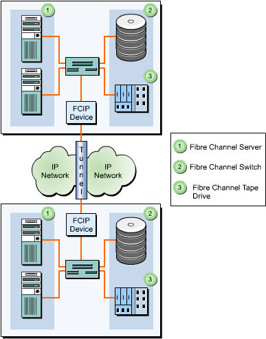
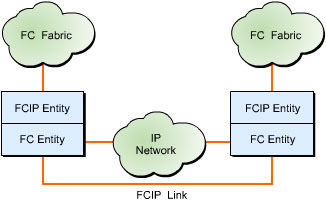
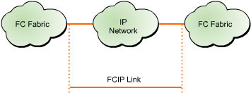
![]() IP addresses and TCP connections are utilized only at the FCIP tunneling devices placed at each end of the IP network, as shown in Figure 5-1-1:
IP addresses and TCP connections are utilized only at the FCIP tunneling devices placed at each end of the IP network, as shown in Figure 5-1-1:
![]() An IP address and TCP/IP connectivity between two FCIP devices detect the network connectivity of an IP network. When a fibre channel node in a SAN needs to communicate with a fibre channel node in a remote SAN, the FCIP device encapsulates the entire fibre channel frame in TCP segments and delivers it across the IP network. At the destination node, the IP and TCP headers are separated and a native fibre channel frame is delivered to the destination fibre channel node through the fibre channel switches available.
An IP address and TCP/IP connectivity between two FCIP devices detect the network connectivity of an IP network. When a fibre channel node in a SAN needs to communicate with a fibre channel node in a remote SAN, the FCIP device encapsulates the entire fibre channel frame in TCP segments and delivers it across the IP network. At the destination node, the IP and TCP headers are separated and a native fibre channel frame is delivered to the destination fibre channel node through the fibre channel switches available.
![]() TCP is used to transfer data across the IP tunnel and to check the occurrence of network congestion. The FCIP devices between remote SANs use the TCP connection to build a virtual interswitch link between them to transfer fibre channel data.
TCP is used to transfer data across the IP tunnel and to check the occurrence of network congestion. The FCIP devices between remote SANs use the TCP connection to build a virtual interswitch link between them to transfer fibre channel data.
 FCIP Interface
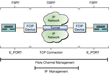
![]() An FCIP tunneling device that interconnects various fibre channel SANs acts as an interface. FCIP uses the Fabric Shortest Path First (FSPF) routing protocol, the Open Shortest Path First (OSPF) routing protocol, and the standard fabric E_PORT switch to interface among SANs. These interfaces conform to fibre channel switch standard requirements for building a switched fibre channel fabric. Multiple FCIP interfaces help combine multiple SAN networks to form a single, logical SAN. Figure 5-1-2 shows how two fibre channel switches form an integrated fabric in which the storage name and server information are exchanged, and data transfer routes are preserved so that a single data storage center is formed:
An FCIP tunneling device that interconnects various fibre channel SANs acts as an interface. FCIP uses the Fabric Shortest Path First (FSPF) routing protocol, the Open Shortest Path First (OSPF) routing protocol, and the standard fabric E_PORT switch to interface among SANs. These interfaces conform to fibre channel switch standard requirements for building a switched fibre channel fabric. Multiple FCIP interfaces help combine multiple SAN networks to form a single, logical SAN. Figure 5-1-2 shows how two fibre channel switches form an integrated fabric in which the storage name and server information are exchanged, and data transfer routes are preserved so that a single data storage center is formed:
| Note | |
![]() If the FCIP tunnel interface goes down, the fibre channel switches on each side of the network disable E_PORTs connected to FCIP devices. Each fabric switch establishes its own SAN in isolation, and transmits a state change notification to the associated end nodes. In this way, each SAN obtains its own switch. As a result, the fabric addressing technique can be reassigned. Connection between remote fibre channel switches is not automatic. To re-establish the connection, you reboot either of the fabric switches after the FCIP tunneling device starts functioning again.
If the FCIP tunnel interface goes down, the fibre channel switches on each side of the network disable E_PORTs connected to FCIP devices. Each fabric switch establishes its own SAN in isolation, and transmits a state change notification to the associated end nodes. In this way, each SAN obtains its own switch. As a result, the fabric addressing technique can be reassigned. Connection between remote fibre channel switches is not automatic. To re-establish the connection, you reboot either of the fabric switches after the FCIP tunneling device starts functioning again.
 Current Status of FCIP
![]() FCIP products are currently available for deployment and private storage. By making complete utilization of the existing fibre channel-based SAN setup, FCIP provides good performance and security and easy network management. FCIP is considered a complementary technology to the existing fibre channel and can be deployed with ease.
FCIP products are currently available for deployment and private storage. By making complete utilization of the existing fibre channel-based SAN setup, FCIP provides good performance and security and easy network management. FCIP is considered a complementary technology to the existing fibre channel and can be deployed with ease.
![]() FCIP plays an important role in IP-based SAN strategies because it provides the feature of extending the fibre channel technology to enable data transfer over WAN. It also provides value-added support for easy integration and creation of a truly global storage network for an enterprise. FCIP extends the range of fibre channel, which has a physical limit of roughly 67 miles, by utilizing the technology of IP routing. With a clear and established network for fibre channel, the FCIP technology supports easy deployment of SAN to implement virtual storage.
FCIP plays an important role in IP-based SAN strategies because it provides the feature of extending the fibre channel technology to enable data transfer over WAN. It also provides value-added support for easy integration and creation of a truly global storage network for an enterprise. FCIP extends the range of fibre channel, which has a physical limit of roughly 67 miles, by utilizing the technology of IP routing. With a clear and established network for fibre channel, the FCIP technology supports easy deployment of SAN to implement virtual storage.
 Future Growth Potential of FCIP
![]() Implementing FCIP helps connect remotely placed SANs using minimum expenditure. The more the implementation of fibre channel SANs that are remotely situated and that need to be a part of the central framework, the greater would be the implementation of FCIP. This implementation of FCIP would also result in increased utilization of fibre channel-based SAN because of the feature of centralized storage and management for an enterprise network.
Implementing FCIP helps connect remotely placed SANs using minimum expenditure. The more the implementation of fibre channel SANs that are remotely situated and that need to be a part of the central framework, the greater would be the implementation of FCIP. This implementation of FCIP would also result in increased utilization of fibre channel-based SAN because of the feature of centralized storage and management for an enterprise network.
![]() In the future, SAN interconnectivity through FCIP may help provide a high-performance, high-reliability infrastructure that assists in the operations of a wide range of companies.
In the future, SAN interconnectivity through FCIP may help provide a high-performance, high-reliability infrastructure that assists in the operations of a wide range of companies.
![]() The following activities may prove to be beneficial for the growth of FCIP:
The following activities may prove to be beneficial for the growth of FCIP:
-
 Extending investments made on the existing technology.
 -
 Extending network services being offered to existing end users.
 -
 Making network services more user-friendly and improving the quality of service and delivery of data.
 FCIP Quality of Service
![]() Quality of service refers to the handling of data as it passes through a shared network. It is a measure of good quality service for data transfer on a network and reducing latency and packet dropping. Using quality of service, you can establish data priority and provide a guaranteed bandwidth for fast delivery.
Quality of service refers to the handling of data as it passes through a shared network. It is a measure of good quality service for data transfer on a network and reducing latency and packet dropping. Using quality of service, you can establish data priority and provide a guaranteed bandwidth for fast delivery.
![]() Techniques used to ensure quality of service include:
Techniques used to ensure quality of service include:
-
 Multi-Protocol Label Switching (MPLS): Establishes a path for the fast transfer of data on a network and enforces quality of service using packet labeling.
 -
 Differentiated Services Architecture (Diffserv): Redefines the Type of Service (TOS) field in the IP header to support Differentiated Services Code Point (DSCP). This support helps provide data delivery with good quality of service. Diffserv enables you to set the priority of network traffic depending on the policy used to establish the quality of service.
 -
IEEE 802.1p: Assigns a priority to an FCIP frame and is enforced through buffer queuing in IP switches. The use of a weighted round-robin queuing algorithm ensures transfer of data including low-priority data in high-priority traffic.
Advantages and Disadvantages of FCIP
Among various technologies that interconnect SANs, FCIP is the most cost-effective technology. The IP technology in FCIP provides the flexibility of network storage and can be used for operations such as remote backup and storage. As a result, FCIP helps increase SAN interconnectivity for supporting a large number of network-based applications.
FCIP also provides support for the existing fibre channel infrastructure. This support helps in the seamless integration of existing SANs over long distances through IP networks and as a result, provides a cost-effective way to secure an enterprise network.
Some advantages of FCIP are that it:
-
Provides a standardized and cost-effective way to develop and deploy SAN interconnection for a wide range of applications.
-
Handles all the routing functions between logical links and systematic delivery of data packets to the specified device.
-
Supports all fibre channel-related services, such as FSPF routing algorithms.
-
Hides information regarding the data packet being routed from the IP network.
-
Interconnects remote SANs, which makes them appear as a large SAN, and helps manage them using traditional SAN management applications.
-
Enables SAN applications, such as disk mirroring or remote replication of data between two enterprise networks, to support other existing protocols without requiring alteration.
-
Supports routing algorithms, such as OSPF, which helps set an alternate path during IP link failure.
-
Provides Cyclic Redundancy Check (CRC) mechanisms for effective resynchronization of data if there is any data loss due to network failures.
Some disadvantages of FCIP are that it:
-
Lacks security and manageability of FCIP-based SAN networks due to the visibility of all network components required for configuration, resulting in misuse and intrusion by unauthorized agents.
-
Does not provide full interoperability with existing vendors of fibre channel end devices.
-
Lacks scalability due to the support for only a few SAN networks at a time.
-
Does not provide a path for data migration from fibre channel to IP-based SANs.
Components of FCIP
![]() Some of the important components of FCIP are:
Some of the important components of FCIP are:
![]() These components work in coordination with each other to transfer a fibre channel frame over an IP network. FCIP Entity should be used in conjunction with Fibre Channel Entity to tunnel the fibre channel fabric over an IP network.
These components work in coordination with each other to transfer a fibre channel frame over an IP network. FCIP Entity should be used in conjunction with Fibre Channel Entity to tunnel the fibre channel fabric over an IP network.
 FCIP Entity and Fibre Channel Entity
![]() FCIP Entity is a network component that exchanges the fibre channel fabric on an IP network using the FCIP protocol. It consists of FCIP link end points, an FCIP control, and service modules. FCIP link end points provide support for fibre channel frames encapsulation and transmission features. The control and services module manages the link initialization and link dissolution of FCIP. It also supports Fibre Channel Entity by linking with important IP network services, such as establishing TCP connectivity, network security, and dynamic discovery of FCIP entities.
FCIP Entity is a network component that exchanges the fibre channel fabric on an IP network using the FCIP protocol. It consists of FCIP link end points, an FCIP control, and service modules. FCIP link end points provide support for fibre channel frames encapsulation and transmission features. The control and services module manages the link initialization and link dissolution of FCIP. It also supports Fibre Channel Entity by linking with important IP network services, such as establishing TCP connectivity, network security, and dynamic discovery of FCIP entities.
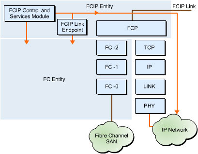
![]() Integration of Fibre Channel Entity with FCIP Entity leads to the formation of a network framework that acts as an interface for the fibre channel fabric and IP network. This interface tunnels the fibre channel fabric through an IP network. The integration of an FCIP link endpoint with two Fibre Channel and FCIP Entity pairs helps transport non-fibre channel structure among various fibre channel devices. To support this transport, FCIP Entity uses a combination of a TCP port and an IP address to establish TCP connections, as shown in Figure 5-1-3:
Integration of Fibre Channel Entity with FCIP Entity leads to the formation of a network framework that acts as an interface for the fibre channel fabric and IP network. This interface tunnels the fibre channel fabric through an IP network. The integration of an FCIP link endpoint with two Fibre Channel and FCIP Entity pairs helps transport non-fibre channel structure among various fibre channel devices. To support this transport, FCIP Entity uses a combination of a TCP port and an IP address to establish TCP connections, as shown in Figure 5-1-3:
![]() Figure 5-1-4 shows how FCIP Entity receives a TCP connect request through FCIP link end points. FCIP Entity consists of a combination of a TCP port and an IP address to establish TCP connections. A fibre channel fabric that acts as an interface to the IP network provides each Fibre Channel and FCIP Entity pair with a unique combination of a fibre channel fabric entity world wide identifier. The integration of the Fibre Channel Entity world wide name with the pair of Fibre Channel and FCIP Entity identifier fields helps identify all Fibre Channel and FCIP Entity pairs existing on an IP-based network.
Figure 5-1-4 shows how FCIP Entity receives a TCP connect request through FCIP link end points. FCIP Entity consists of a combination of a TCP port and an IP address to establish TCP connections. A fibre channel fabric that acts as an interface to the IP network provides each Fibre Channel and FCIP Entity pair with a unique combination of a fibre channel fabric entity world wide identifier. The integration of the Fibre Channel Entity world wide name with the pair of Fibre Channel and FCIP Entity identifier fields helps identify all Fibre Channel and FCIP Entity pairs existing on an IP-based network.
 Data Engine in FCIP
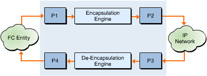
![]() The FCIP data engine helps manage the tasks related to fibre channel frame encapsulation and de-encapsulation. It also manages the transmission of FCIP frames over a single TCP connection. Figure 5-1-5 shows a model of the FCIP data engine in an FCIP link endpoint:
The FCIP data engine helps manage the tasks related to fibre channel frame encapsulation and de-encapsulation. It also manages the transmission of FCIP frames over a single TCP connection. Figure 5-1-5 shows a model of the FCIP data engine in an FCIP link endpoint:
![]() In Figure 5-1-5, the portals used in the FCIP data engine are:
In Figure 5-1-5, the portals used in the FCIP data engine are:
-
 Fibre Channel Frame Receiver Portal (P1): Point from which a fibre channel frame and time stamp values pass to an FCIP data engine from Fibre Channel Entity.
 -
 Fibre Channel Frame Transmitter Portal (P4): Point from which a reconstituted fibre channel frame and time stamp values emerges from an FCIP data engine to Fibre Channel Entity.
 -
 Encapsulated Frame Transmitter Portal (P2): Point from which an FCIP frame is transported to the IP network by an FCIP data engine.
 -
 Encapsulated Frame Receiver Portal (P3): Point from which an FCIP data engine receives an FCIP frame from the IP network.
![]() These portals do not process or validate the data that pass through them. The portals are the named access points which the FCIP data engine links to the external network.
These portals do not process or validate the data that pass through them. The portals are the named access points which the FCIP data engine links to the external network.
![]() The flow of data through a pair of IP networks connected to FCIP data engines is discharged as:
The flow of data through a pair of IP networks connected to FCIP data engines is discharged as:
-
 The fibre channel frame-receiving portal receives the fibre channel frame with the time stamp. The frame and time stamp are then transferred to the encapsulation engine. Fibre Channel Entity processes the received frame according to fibre channel rules. The FCIP data engine does not verify the fibre channel frame.
 -
 The received frame and time stamp are arranged as per the encapsulation format for data transmission over the IP network.
 -
 The encapsulated frame transmitter portal receives the complete encapsulated frame and inserts the frame within the TCP byte stream.
Note  The transmission of the FCIP frame over the IP network conforms to all the TCP rules of operation.
 -
 The data engine of FCIP Entity receives the frame through the encapsulated frame receiver portal. This frame is then transferred to the de-encapsulation engine for additional processing.
 -
 The de-encapsulation engine verifies the received TCP byte streams. The received frame and time stamp are then de-encapsulated.
 -
 The de-encapsulated frame and time stamp are transferred to the fibre channel frame transmitter portal. From this portal, Fibre Channel Entity receives the frame with the time stamp.
 Link Endpoint in FCIP
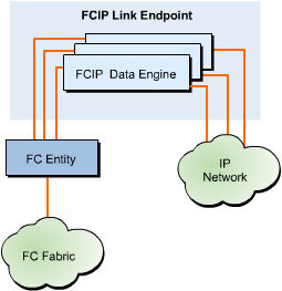
![]() The FCIP link endpoint is an integral part of FCIP Entity and consists of one or more FCIP data engines. Each FCIP link is individually managed by an FCIP link endpoint. The FCIP link endpoint is a type of data translation endpoint between Fibre Channel Entity and an IP network. An FCIP link is formed when two FCIP link end points communicate with one or more TCP connections. This link helps connect two isolated SANs related to a fibre channel fabric and form a single fibre channel fabric. The FCIP link endpoint has a single FCIP data engine related to each TCP connection available in the FCIP link, as shown in Figure 5-1-6:
The FCIP link endpoint is an integral part of FCIP Entity and consists of one or more FCIP data engines. Each FCIP link is individually managed by an FCIP link endpoint. The FCIP link endpoint is a type of data translation endpoint between Fibre Channel Entity and an IP network. An FCIP link is formed when two FCIP link end points communicate with one or more TCP connections. This link helps connect two isolated SANs related to a fibre channel fabric and form a single fibre channel fabric. The FCIP link endpoint has a single FCIP data engine related to each TCP connection available in the FCIP link, as shown in Figure 5-1-6:
![]() When a TCP connection is established with a new Fibre Channel and FCIP Entity pair, FCIP Entity of the pair forms a new FCIP link endpoint with only one FCIP data engine. The two FCIP link end points communicate with each other over an IP network, regardless of the fibre channel payloads that they carry. Similarly, fibre channel end nodes are connected to the fibre channel fabric regardless of the TCP/IP-based communication used by the fibre channel fabric. The FCIP link endpoint uses TCP-based flow control techniques to manage its internal resources. To control the flow of data, the FCIP link endpoint communicates with its local Fibre Channel Entity.
When a TCP connection is established with a new Fibre Channel and FCIP Entity pair, FCIP Entity of the pair forms a new FCIP link endpoint with only one FCIP data engine. The two FCIP link end points communicate with each other over an IP network, regardless of the fibre channel payloads that they carry. Similarly, fibre channel end nodes are connected to the fibre channel fabric regardless of the TCP/IP-based communication used by the fibre channel fabric. The FCIP link endpoint uses TCP-based flow control techniques to manage its internal resources. To control the flow of data, the FCIP link endpoint communicates with its local Fibre Channel Entity.
Frame in FCIP
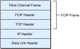
An FCIP frame is the direct encapsulation of a fibre channel frame, as shown in Figure 5-1-7. The fibre channel header, the start of frame (SOF) and end of frame (EOF) delimiters, fibre channel CRC, and fibre channel data are not modified or manipulated by FCIP. The frame is carried in its original format. FCIP uses a fibre channel encapsulation frame header that consists of identifier fields for the FCIP protocol and the version level. The frame length field of FCIP frame contains the value for the length of the fibre channel frame and the encapsulation header. This frame length value helps check the receipt of an intact fibre channel frame.
The TCP header and the FCIP device check for the systematic transfer of data by regulating fibre channel EOF and SOF, as shown in Figure 5-1-8. The validation of the EOF, SOF, and FCIP frame length field ensures that the FCIP devices existing on both sides of an IP network to send and receive data are in synchronized state.
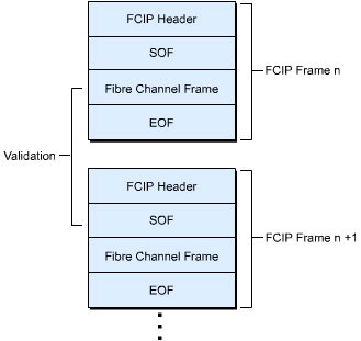
Figure 5-1-8: Regulation of EOF, SOF, and FCIP Frame Length
Structure of FCIP
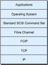
![]() FCIP provides fibre channel tunneling over a TCP/IP network. It encapsulates the fibre channel frame into IP packets and maps fibre channel fabrics to IP addresses. The structure of FCIP is similar to a protocol stack in hierarchical format, as shown in Figure 5-1-9. In this protocol stack, the FCIP layer lies between the TCP and fibre channel layers. FCIP enables the use of the existing fibre channel hardware and software infrastructure and helps access SAN-connected data over the IP network.
FCIP provides fibre channel tunneling over a TCP/IP network. It encapsulates the fibre channel frame into IP packets and maps fibre channel fabrics to IP addresses. The structure of FCIP is similar to a protocol stack in hierarchical format, as shown in Figure 5-1-9. In this protocol stack, the FCIP layer lies between the TCP and fibre channel layers. FCIP enables the use of the existing fibre channel hardware and software infrastructure and helps access SAN-connected data over the IP network.
 Network Model of FCIP
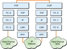
![]() The primary purpose of the FCIP protocol is to create and administer multiple FCIP links to transfer data from SAN to SAN. The basic functions of FCIP Entity are to forward fibre channel frames and perform the task of fibre channel frame encapsulation. Figure 5-1-10 shows the FCIP network model:
The primary purpose of the FCIP protocol is to create and administer multiple FCIP links to transfer data from SAN to SAN. The basic functions of FCIP Entity are to forward fibre channel frames and perform the task of fibre channel frame encapsulation. Figure 5-1-10 shows the FCIP network model:
![]() The FCIP link is a service supported by FCIP for use in interconnectivity with fibre channel fabrics. This link service helps connect two different sections of the fibre channel fabric by utilizing the services of an IP network as a transport medium and creates a fibre channel fabric, as shown in Figure 5-1-11. FCIP Entity combines with Fibre Channel Entity where the FCIP link meets the fibre channel fabric. This location acts as the point of connectivity between the fibre channel fabric and an IP network.
The FCIP link is a service supported by FCIP for use in interconnectivity with fibre channel fabrics. This link service helps connect two different sections of the fibre channel fabric by utilizing the services of an IP network as a transport medium and creates a fibre channel fabric, as shown in Figure 5-1-11. FCIP Entity combines with Fibre Channel Entity where the FCIP link meets the fibre channel fabric. This location acts as the point of connectivity between the fibre channel fabric and an IP network.
 TCP/IP Connectivity in FCIP
![]() When FCIP Entity creates and establishes a TCP connection, it searches for the IP address with which the TCP connection is to be made. It then establishes all the enabled IP security features for that IP address. Service Location Protocol (SLPv2) can be used for the dynamic discovery of FCIP entities. The tasks that FCIP Entity performs after enabling the IP security features for the SLPv2 discovery process are:
When FCIP Entity creates and establishes a TCP connection, it searches for the IP address with which the TCP connection is to be made. It then establishes all the enabled IP security features for that IP address. Service Location Protocol (SLPv2) can be used for the dynamic discovery of FCIP entities. The tasks that FCIP Entity performs after enabling the IP security features for the SLPv2 discovery process are:
-
 Finding one or more FCIP discovery domains for utilization in the dynamic discovery process
 -
 Establishing an SLPv2 service agent for FCIP Entity to all peer FCIP entities in the FCIP discovery domains being found
 -
 Establishing an SLPv2 user agent to locate service advertisements for peer FCIP entities in the identified FCIP discovery domains
Note  SLPv2 is a protocol that helps organize and find resources, such as printers, tape drives, disk drives, and databases, in a network environment.
![]() For each peer FCIP Entity that is found dynamically by utilizing the services of an SLPv2 user agent, IP security features are established for the new TCP/IP address being found.
For each peer FCIP Entity that is found dynamically by utilizing the services of an SLPv2 user agent, IP security features are established for the new TCP/IP address being found.
![]() The information regarding the new TCP connection includes:
The information regarding the new TCP connection includes:
-
 Target fibre channel fabric entity World Wide Name of the Fibre Channel and FCIP Entity pair with which the TCP connection is to be established
 -
 Parameters of TCP connection
 -
 Information regarding the quality of service
![]() Depending on the information being collected, FCIP Entity creates a TCP connection request to the FCIP port of 3225 at the IP address that the SLPv2 service specifies.
Depending on the information being collected, FCIP Entity creates a TCP connection request to the FCIP port of 3225 at the IP address that the SLPv2 service specifies.
![]() If the requested TCP connection is not accepted, steps should be taken to reduce the number of unnecessary repeated attempts to create similar type of connections. If the requested TCP connection is accepted, FCIP Entity completes the establishment of a new FCIP data engine.
If the requested TCP connection is not accepted, steps should be taken to reduce the number of unnecessary repeated attempts to create similar type of connections. If the requested TCP connection is accepted, FCIP Entity completes the establishment of a new FCIP data engine.
![]() A new TCP connection should not be initiated by FCIP Entity if the incoming TCP connect request is already accepted from the same FCIP Entity. FCIP Entity should support a technique to acknowledge the receipt of a TCP connection request so that Fibre Channel Entity is in a position to stop an existing TCP connection whenever required. This enables Fibre Channel Entity to end all requests for TCP connections that are causing errors.
A new TCP connection should not be initiated by FCIP Entity if the incoming TCP connect request is already accepted from the same FCIP Entity. FCIP Entity should support a technique to acknowledge the receipt of a TCP connection request so that Fibre Channel Entity is in a position to stop an existing TCP connection whenever required. This enables Fibre Channel Entity to end all requests for TCP connections that are causing errors.
 Flow Control in FCIP
![]() FCIP lies between the fibre channel fabric and IP network. As a result, there is a possibility of network congestion on both sides. To rectify network congestion on the IP side, FCIP uses the established flow control methods of TCP. Although a specific mechanism is not available for FCIP flow control, the standard TCP sliding window mechanism for flow control can be used at the destination fibre channel SAN.
FCIP lies between the fibre channel fabric and IP network. As a result, there is a possibility of network congestion on both sides. To rectify network congestion on the IP side, FCIP uses the established flow control methods of TCP. Although a specific mechanism is not available for FCIP flow control, the standard TCP sliding window mechanism for flow control can be used at the destination fibre channel SAN.
![]() For example, if a receiving fibre channel switch does not have enough buffer space to receive inbound frames from the FCIP destination device, the device can suspend additional transmission of frames. Similarly, if a fibre channel switch is to deliver fibre channel frames beyond its limitations, you can manage the buffer size to slow down the rate of frame transmission by the originating fibre channel device.
For example, if a receiving fibre channel switch does not have enough buffer space to receive inbound frames from the FCIP destination device, the device can suspend additional transmission of frames. Similarly, if a fibre channel switch is to deliver fibre channel frames beyond its limitations, you can manage the buffer size to slow down the rate of frame transmission by the originating fibre channel device.
![]() If compatible line speeds with IP and fibre channel exist, the operation of FCIP involves both fibre channel flow control and TCP flow control mechanisms initiated by fibre channel SAN applications. At times, there may be inadequate bandwidth across the IP network or congested network on the destination SAN. These mechanisms are mutually dependent as the application of TCP flow control at one end initiates the fibre channel flow control at the other end.
If compatible line speeds with IP and fibre channel exist, the operation of FCIP involves both fibre channel flow control and TCP flow control mechanisms initiated by fibre channel SAN applications. At times, there may be inadequate bandwidth across the IP network or congested network on the destination SAN. These mechanisms are mutually dependent as the application of TCP flow control at one end initiates the fibre channel flow control at the other end.
 Time-Out Values in FCIP
![]() FCIP provides ordinary tunneling of fibre channel frames, and it is governed by fibre channel communication rules. FCIP uses the error detect time-out value (E_D_TOV) to monitor the regular and correct flow of frame sets within a fibre channel network. If the next fibre channel frame within a network could not be issued within E_D_TOV, an error is generated that results in the retransmission of the entire set of frame. The default value of E_D_TOV is set to 10 seconds, which can be changed during port logon operation and depends on the fibre channel implementation.
FCIP provides ordinary tunneling of fibre channel frames, and it is governed by fibre channel communication rules. FCIP uses the error detect time-out value (E_D_TOV) to monitor the regular and correct flow of frame sets within a fibre channel network. If the next fibre channel frame within a network could not be issued within E_D_TOV, an error is generated that results in the retransmission of the entire set of frame. The default value of E_D_TOV is set to 10 seconds, which can be changed during port logon operation and depends on the fibre channel implementation.
![]() In addition to E_D_TOV, fibre channel standards help set a longer time-out value, which is known as resource allocation time-out value (R_A_TOV). The R_A_TOV value is initially set to 10 seconds. Its focus is on resources that were not delivered properly due to communication failure. Each time a failure in communications occurs, the operation does not resume until all the pending transmissions are completed.
In addition to E_D_TOV, fibre channel standards help set a longer time-out value, which is known as resource allocation time-out value (R_A_TOV). The R_A_TOV value is initially set to 10 seconds. Its focus is on resources that were not delivered properly due to communication failure. Each time a failure in communications occurs, the operation does not resume until all the pending transmissions are completed.
 Error Handling in FCIP
![]() FCIP is an opaque transport mechanism that makes the content of fibre channel frames invisible. It transfers the generated content from one SAN to the destination SAN without performing the task of checking errors in the fibre channel layer. Even low-level error conditions, such as CRC errors, are transferred from source to destination locations. Other types of errors that occur at one end of the fibre channel network are distributed to the other end of the network through FCIP. These errors make the connected network congested with excessive errors.
FCIP is an opaque transport mechanism that makes the content of fibre channel frames invisible. It transfers the generated content from one SAN to the destination SAN without performing the task of checking errors in the fibre channel layer. Even low-level error conditions, such as CRC errors, are transferred from source to destination locations. Other types of errors that occur at one end of the fibre channel network are distributed to the other end of the network through FCIP. These errors make the connected network congested with excessive errors.
![]() But, FCIP manages the errors that are generated over the IP network. As per the FCIP specification, the occurrence of a frame error in the FCIP encapsulation layer causes that frame to be dropped by the receiving FCIP end device of the IP network. This prevents an IP-generated error from being transferred to the destination fibre channel SAN.
But, FCIP manages the errors that are generated over the IP network. As per the FCIP specification, the occurrence of a frame error in the FCIP encapsulation layer causes that frame to be dropped by the receiving FCIP end device of the IP network. This prevents an IP-generated error from being transferred to the destination fibre channel SAN.
![]() In all potential connection error conditions, the FCIP specification does not allow the retransmission of FCIP frames from a previous connection after a new connection is established. This prevents frame duplication at the receiving fibre channel end device and eliminates the time-consuming recovery processes.
In all potential connection error conditions, the FCIP specification does not allow the retransmission of FCIP frames from a previous connection after a new connection is established. This prevents frame duplication at the receiving fibre channel end device and eliminates the time-consuming recovery processes.
Security in FCIP
![]() Security in FCIP is provided using security keys and authentication. FCIP utilizes the services of the IPSec protocol to support features such as data secrecy and authentication services and the Internet Key Exchange (IKE) protocol for key management.
Security in FCIP is provided using security keys and authentication. FCIP utilizes the services of the IPSec protocol to support features such as data secrecy and authentication services and the Internet Key Exchange (IKE) protocol for key management.
| Note | |
![]() IKE is a protocol that implements Oakley and Skeme key exchanges within the Internet Security Association and Key Management Protocol (ISAKMP) framework. It supports the authentication of IPSec peers, negotiates IPSec keys, and IPSec Security Associations (SAs).
IKE is a protocol that implements Oakley and Skeme key exchanges within the Internet Security Association and Key Management Protocol (ISAKMP) framework. It supports the authentication of IPSec peers, negotiates IPSec keys, and IPSec Security Associations (SAs).
![]() ISAKMP is a protocol framework that specifies the payload formats with the mechanism of implementing the key exchange protocol and negotiation of SA.
ISAKMP is a protocol framework that specifies the payload formats with the mechanism of implementing the key exchange protocol and negotiation of SA.
![]() Oakley is a key exchange protocol that defines the derivation of authenticated keying material.
Oakley is a key exchange protocol that defines the derivation of authenticated keying material.
![]() Skeme is a key exchange protocol that defines the derivation of authenticated keying material with rapid key refreshment.
Skeme is a key exchange protocol that defines the derivation of authenticated keying material with rapid key refreshment.
![]() SA specifies the utilization of security services for secured communications between two or more network components.
SA specifies the utilization of security services for secured communications between two or more network components.
 Security Keys in FCIP
![]() FCIP entities support IKE to perform tasks, such as peer authentication, negotiation of SA, and key management, using IPSec Domain of Interpretation (DOI). The task of manual keying should not be used to create SA because it does not provide the required elements for rekeying.
FCIP entities support IKE to perform tasks, such as peer authentication, negotiation of SA, and key management, using IPSec Domain of Interpretation (DOI). The task of manual keying should not be used to create SA because it does not provide the required elements for rekeying.
![]() FCIP entities support:
FCIP entities support:
-
 Preshared IKE keys
 -
 Certificate-based peer authentication using digital signatures
 -
 No peer authentication using public key encryption methods
![]() If the services of preshared keys are used, IKE Main Mode should be utilized only when both peers of an FCIP link use the statically assigned IP addresses. The use of dynamically assigned IP addresses with Main Mode can result in the FCIP deployment being hacked. If the peer of an FCIP link uses the dynamically assigned IP address, Aggressive Mode, and not Main Mode, should be used. If digital signatures are used, either IKE Main Mode or IKE Aggressive Mode can be used.
If the services of preshared keys are used, IKE Main Mode should be utilized only when both peers of an FCIP link use the statically assigned IP addresses. The use of dynamically assigned IP addresses with Main Mode can result in the FCIP deployment being hacked. If the peer of an FCIP link uses the dynamically assigned IP address, Aggressive Mode, and not Main Mode, should be used. If digital signatures are used, either IKE Main Mode or IKE Aggressive Mode can be used.
![]() To establish a fully secured FCIP link, the participating FCIP entities use Security Policy Database (SPD). FCIP entities contain multiple interfaces and IP addresses and can establish multiple TCP connections with different FCIP end points and IP addresses. The presence of a multiple interface results in the establishment of IKE Phase 1 SA for each pair of FCIP endpoint and IP address.
To establish a fully secured FCIP link, the participating FCIP entities use Security Policy Database (SPD). FCIP entities contain multiple interfaces and IP addresses and can establish multiple TCP connections with different FCIP end points and IP addresses. The presence of a multiple interface results in the establishment of IKE Phase 1 SA for each pair of FCIP endpoint and IP address.
| Note | |
![]() On successful IKE negotiations, both FCIP entities store SA parameters in the SA Database (SAD) that contains a set of active SA entries. Each entry contains information, such as Sequence Counter Overflow, Sequence Number Counter, Anti-replay Window, and Lifetime of SA. A default of one-hour SA Lifetime is used by FCIP entities with a default Anti-replay window of 32 sequence numbers.
On successful IKE negotiations, both FCIP entities store SA parameters in the SA Database (SAD) that contains a set of active SA entries. Each entry contains information, such as Sequence Counter Overflow, Sequence Number Counter, Anti-replay Window, and Lifetime of SA. A default of one-hour SA Lifetime is used by FCIP entities with a default Anti-replay window of 32 sequence numbers.
 Authenticating with IPSec ESP and Replay Protection
![]() FCIP entities need information from the IPSec Encapsulating Security Payload (ESP) header in tunnel mode or transport mode to support data integrity and secrecy. IPSec ESP for message authentication calculates a value for cryptographic hash on a protected payload.
FCIP entities need information from the IPSec Encapsulating Security Payload (ESP) header in tunnel mode or transport mode to support data integrity and secrecy. IPSec ESP for message authentication calculates a value for cryptographic hash on a protected payload.
![]() To support IPSec ESP message authentication, FCIP entities need to implement:
To support IPSec ESP message authentication, FCIP entities need to implement:
-
 Hash Message Authentication Code (HMAC) with Secure Hash Algorithm-1 (SHA-1)
 -
 Advanced Encryption Standard (AES) in Cipher Block Chaining (CBC) and Message Authentication Code (MAC) modes with eXtended Cipher Block Code (XCBC) extensions
![]() To support IPSec ESP secrecy, FCIP entities need to implement:
To support IPSec ESP secrecy, FCIP entities need to implement:
-
 Triple Data Encryption Standard (3DES) in CBC mode
 -
 AES in Counter (CTR) mode
 -
 NULL encryption
![]() FCIP entities need to support replay protection against any possible ESP sequence number wrap. In addition, depending upon the cipher algorithm and the number of bits in the cipher block size, the validity of the key may be compromised. In both the situations, SA needs to be re-established.
FCIP entities need to support replay protection against any possible ESP sequence number wrap. In addition, depending upon the cipher algorithm and the number of bits in the cipher block size, the validity of the key may be compromised. In both the situations, SA needs to be re-established.
![]() FCIP entities need to use the result of an IKE Phase 1 negotiation to start an IKE Phase 2 quick mode exchange and establish new SAs. After creating Security Parameter Index (SPI) for the IP network, the originating device starts using this SPI for all the new FCIP encapsulated frames. Frames that are either in transit or resent due to TCP retransmissions can use either the new SPI or the one being replaced.
FCIP entities need to use the result of an IKE Phase 1 negotiation to start an IKE Phase 2 quick mode exchange and establish new SAs. After creating Security Parameter Index (SPI) for the IP network, the originating device starts using this SPI for all the new FCIP encapsulated frames. Frames that are either in transit or resent due to TCP retransmissions can use either the new SPI or the one being replaced.
| Note | |
 Security Association and Data Security Issues
![]() All TCP connections need to be secured by IKE Phase 2 SA. Network traffic from multiple TCP connections flow within each IPSec Phase 2 SA. Although it is possible for IKE Phase 2 SA to protect more than one TCP connection, all the packets of a TCP connection are protected using just one IKE Phase 2 SA. If different qualities of service settings are used for establishing TCP connections, different IPSec SA connections should be used.
All TCP connections need to be secured by IKE Phase 2 SA. Network traffic from multiple TCP connections flow within each IPSec Phase 2 SA. Although it is possible for IKE Phase 2 SA to protect more than one TCP connection, all the packets of a TCP connection are protected using just one IKE Phase 2 SA. If different qualities of service settings are used for establishing TCP connections, different IPSec SA connections should be used.
![]() Before you implement FCIP:
Before you implement FCIP:
-
 The IP addresses and port numbers in the data packet should be checked to be similar to any of the locally stored per-connection values.
 -
 The IPSec layer should perform the validation operation. An FCIP implementation can perform several IKE Phase 2 negotiations and cache them in its local SPIs and release as per the current SA lifetime settings.
![]() The use of an IP network in a SAN as a replacement for physical cabling has some inherent security problems. The cabling system used in a fibre channel network is physically protected from outside access whereas IP networks are not. With IP networks, there are numerous ways in which the security setup of communication networks can be broken.
The use of an IP network in a SAN as a replacement for physical cabling has some inherent security problems. The cabling system used in a fibre channel network is physically protected from outside access whereas IP networks are not. With IP networks, there are numerous ways in which the security setup of communication networks can be broken.
![]() IP networks carry FCIP links for fibre channel networks. As a result, it is better to provide security in relation to the entire IP network instead of securing only the fibre channel network.
IP networks carry FCIP links for fibre channel networks. As a result, it is better to provide security in relation to the entire IP network instead of securing only the fibre channel network.
![]() The possible security threats by unauthorized agents that need to be considered before deploying FCIP-based fibre channel network are:
The possible security threats by unauthorized agents that need to be considered before deploying FCIP-based fibre channel network are:
-
 Access to network resources through the normal fibre channel fabric and processes
 -
 Monitoring and administering the fibre channel traffic that passes through a physical media used by the IP network
 -
 Hijacking of TCP connections and starting invalid FCIP links between two peer FCIP entities
 -
 Injection of valid and invalid FCIP frames on TCP connections
 -
 Alteration of the payload of an FCIP frame
 -
 Disruption of the functioning of a fibre channel fabric by unauthorized agents simulating as valid FCIP entities
 -
 Denial of service due to excessive TCP connection requests and other resource exhaustion operations
Parameter Issues of TCP Connection
![]() The following considerations regarding the TCP connection parameters must be taken into account to provide better management of an FCIP link end point and FCIP link resources:
The following considerations regarding the TCP connection parameters must be taken into account to provide better management of an FCIP link end point and FCIP link resources:
-
 The selective acknowledgement parameter enables the receiving end in a network setup to acknowledge multiple lost packets in a single acknowledgement. This helps in faster data recovery.
 -
 The TCP window scale option enables TCP window sizes larger than 16-bits to be advertised by the receiving end. An FCIP link end point uses the available techniques to set a window size based on the available local buffer resources and the required throughput.
 -
 FCIP entities should implement protection against wrapped sequence numbers because within a single connection, TCP sequence numbers can wrap within a time-out window.
 -
 FCIP entities should disable Nagle Algorithm by setting the TCP_NODELAY option to 1 at the local TCP interface.
 -
 When idle, the keep-alive option of the TCP connection helps maintain the connection.
 -
 When FCIP Entity finds that a TCP connection is lost, it needs to inform the Fibre Channel Entity of the failure and the reason for it.

