A wide range of products – hardware as well as software – make up a typical Storage Area Network (SAN). While software products, without exception, are a part of the management setup, hardware products comprise hubs, switches, bridges, routers, storage subsystems, and Host Bus Adapters (HBAs). Like any network, cables also form a very important part of a storage network because they interconnect these SAN devices. A proper understanding of the devices mentioned above, applications, and cables will help you build a storage network that meets your requirements.
This ReferencePoint discusses the SAN building blocks. These include the hardware and the software products that are used to build a storage network. The types of cables that are used to interconnect SAN devices also play a very important role in building SANs. However, in order to understand the building blocks of a SAN, a basic understanding of SAN is required. A brief primer introduces you to the concept of SANs and the three SAN topologies: Point-to-Point, Fibre Channel-Arbitrated Loop (FC-AL), and Switched Fabric.
Storage Area Networks (SANs) – A Primer
In the past decade, the amount of data that is transacted has grown exponentially. The biggest problem associated with the storage of this huge amount of data is that the data must be available to end users anywhere and anytime. Another problem associated with data storage is that most of the storage devices are relatively slower than other network components, such as routers and switches. As a result, transaction speed is comparatively slow. This is not only a concern for clients and end users accessing the data, but also for online businesses.
It might seem to many of us that not much data is generated in online transactions. However, according statistics quoted by reliefweb (www.reliefweb.com), a less popular site is hit at least 1000 times at an average. This implies that hugely popular sites, especially those offering free e-mail services, such as Yahoo and Hotmail, record at least a million hits a day.
In this scenario, the basic requirements from a network on which data is stored in large amounts are:
-
High speed of transactions
-
High data availability
-
High overall performance of the network
Industry experts and organizations have worked relentlessly to work out a solution that will help fulfill the requirements from storage networks.
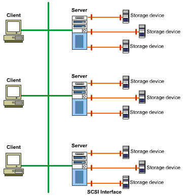
displays the implementation of SCSI-based early storage networks.
SCSI proved to be fast and reliable. However it worked well only with small-sized networks, where the number of nodes was not more than 30-40. In small-sized networks, transaction rates were far below the transaction rates for medium-to-large-sized networks. In addition, since storage devices were a part of the network setup that was accessible to users, unauthorized users could easily access the data stored on storage devices. These disadvantages motivated experts to look for alternative solutions.
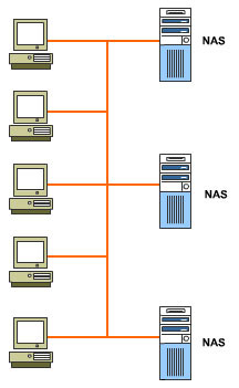
The failure of SCSI led to the concept of Network Attached Storages (NASs). In this solution, special storage devices called NASs were introduced into networks, in addition to existing storage devices. Instead of being directly connected to the servers, NASs were directly connected to the network, as shown in Figure 1-1-2. Since the extra layer of servers was removed from a transaction, the exchange rate increased significantly. NASs proved to be an effective solution and eased a lot of storage-related problems.
However, NAS-based solutions became redundant when severe performance-related problems started to emerge. For example, though a NAS itself is a high-performance device, its performance is severely limited by the available network bandwidth. In addition, NAS devices generate excessive network traffic. In worst cases, this excessive traffic can bring down the overall network productivity and performance. The problem of unauthorized access of data and vulnerability to malicious attacks continued to affect the performance of NAS-based solutions. This is because NASs are directly attached to the rest of the network and, therefore, are vulnerable to such malicious attacks.
SANs are the latest technology in the field of storage networking. The main aim behind the development of SAN technology was to successfully deal with the colossal amount of data that is stored and accessed on corporate networks. In addition, since most of the data stored on these storage devices is critical for an organization from the business perspective, another prime area of focus in SAN-based solutions was to segregate the bulk of storage devices from the rest of the network to minimize the possibility of unauthorized access or malicious attacks.
Dealing with large volumes of data is not very complicated. You can have large number of storage devices to deal with the data. However, the situation becomes a little complicated if you demand superior performance from your network as well. Heavy transactions, such as remote backup and restore operations can slow down the network considerably. This is where SANs come into the picture. They allow you to handle as well as secure enormous amounts of data without having to compromise the overall performance of the network.
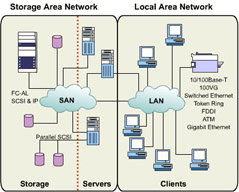
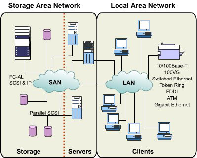
A SAN is a separate network connected to your LAN. All storage devices on your intranet are a part of this network. However, this storage network is well hidden from network clients and users that are a part of your traditional LAN. As a result, end users or unauthorized users with malicious intent are not aware of the separate network, which brings down the possibility of unauthorized access of precious data to a large extent. Figure 1-1-3 depicts the generic representation of a SAN.
This concept of "a network within a network" makes a SAN a highly secure environment for data storage. In addition, a basic requirement of SAN technology is that the storage devices, servers, and other interconnection devices (hubs, routers, gateways, and bridges) that make up your storage network must be high-performance and high-speed devices.
Like any other traditional network, a SAN can be physically arranged in three ways: Point-to-Point, Fibre Channel-Arbitrated Loop (FC-AL), and Switched Fabric.
The Point-to-Point Topology
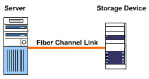
depicts the Point-to-Point SAN topology.
Due to the direct connection between two devices and absence of media sharing, the transactions in the Point-to-Point topology are faster, relatively error-free, and the complete bandwidth of the link is available to the transactions. As a result, this is one of the most reliable SAN topologies.
| Tip | You cannot have a SAN that solely uses the Point-to-Point topology. It is an extremely expensive option and, therefore, you must preferably use this type of connectivity between two very high-speed devices. For example, you can connect two high-end disk arrays using this topology. |
The Fibre Channel-Arbitrated Loop (FC-AL) Topology
This topology may remind you of the ring topology of traditional networks. However, unlike the traditional ring, FC-AL can support a higher number of nodes. Up to 126 devices (or nodes) can be connected to form a complete loop. Figure 1-1-5 displays the organization of the FC-AL topology.
In this topology, if a device needs to communicate with another device, it must arbitrate (or compete) to gain control of the loop. This scenario is very similar to the token-passing method in a traditional ring. After competing successfully for control on the loop, the node establishes a virtual point-to-point connection with the intended destination and begins to transfer data. Because of the virtual point-to-point connection, the communicating nodes can use the full bandwidth of the fiber channel link. When a connection is terminated, the loop becomes available to other nodes.
There is a major disadvantage associated with the FC-AL topology. Because the number of nodes that make up the loop is very high, communication can be very slow.
| Tip | The Fibre Channel loop topology will work in the real world provided the number of nodes connected to the loop is not very high. It is suggested that not more than 20 nodes should be connected in a Fibre Channel loop. |
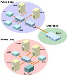
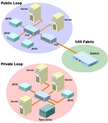
FC-AL loops are of two types, public loops and private loops. Public loops are connected to the rest of SAN fabric and are accessible to nodes that do not belong to the loop. On the other hand, private loops are not a part of the SAN fabric, which makes them inaccessible to other nodes that are not a part of the loop. Figure 1-1-6 depicts the two loops.
The Switched Fabric Topology
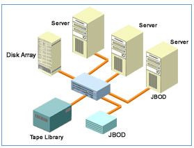
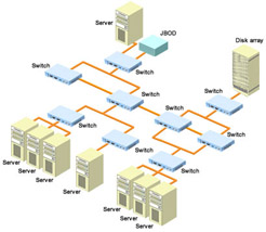
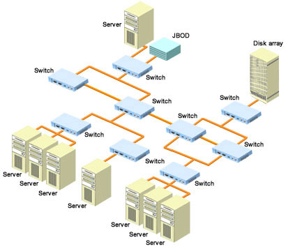
The Switched Fabric topology is based on the use of Fibre Channel switches, where all the switches that are part of the SAN are interconnected to form a fabric, and hence the name "Switched Fabric". Because of many Inter-Switch Links (ISLs), multiple simultaneous transactions are possible. Figure 1-1-7 depicts the Switched Fabric topology of a SAN.
Due to the use of switches this topology can support up to 224 nodes at a time and still not compromise on the performance. This is because each individual port that is connected to the fabric is allocated 100 Mbps full-duplex, dedicated bandwidth.
| Tip | The Switched Fabric topology is the most commonly implemented topology of the three SAN topologies. |
| Note | As a designer of a storage network, you do not need to implement only one topology strictly. You can have an intelligent mix of two or all the three to meet your organization's requirements. |
Hardware Devices
SANs today are predominantly based on Fibre Channel technology. The main reason for the predominance of Fibre Channel technology in SAN environments is that Fibre Channel devices allow you to develop solutions that provide high performance and high availability, which are the fundamental requirements of a storage network. In addition, these Fibre Channel devices also help you effectively combat the problems related to bandwidth, which generally crop up during bulky operations, such as backup and restore operations.
For example, the average amount of data that is transacted in everyday operations in a medium-sized SAN can range from several hundred to thousand Gbps per hour. If you were to use hubs that you use in traditional LANs or even WANs, the load would be too high for them. This is because these hubs can only support data transactions within the range of 10 to 100 Mbps. For networks that transact large amounts of data, such devices can cause major traffic bottlenecks. In the networks where huge amounts of data are exchanged on an hourly basis, you would need Fibre Channel hubs that can not only handle the large volumes of data, but also ensure that the performance of the entire network is not hampered by a slow-performing device.
The devices that make up a storage network are:
-
Host Bus Adapters (HBAs)
-
Fibre Channel connectors
-
Fibre Channel hubs
-
Fibre Channel bridges and multiplexers
-
Fibre Channel routers and gateways
-
Fibre Channel switches
-
Storage devices
-
SAN servers
| Tip | Depending on the configuration of your SAN, you might need to use all the above-stated components or you can skip a few, such as gateways and multiplexers. |
HBAs
HBAs are the equivalent of what are known as network interface cards (NICs) that are used in LANs and other non-SAN networks. They replace the traditional SCSI cards and interconnect SAN devices, such as servers and storage devices, and the rest of your storage network.
Like any NIC, an HBA provides hard-coded, 64-bit Node_Name (World Wide Name or WWN) and Port_Name (World Wide Port Name or WWPN) addresses to a SAN device and its ports. However, HBAs are not exactly what NICs are in a LAN. This is because HBAs provide more functionality than NICs.
HBAs play a major role in the initialization of Fibre Channel devices and ports that belong to an arbitrated loop or Fabric. They also provide support to the upper-level protocols, such as TCP/IP, ensuring successful interaction between SANs and connected LAN(s). Another important function of HBAs is to encode data as per the 8B/10B scheme, which is fast, an extremely secure, and reliable data encoding mechanism. In addition, HBAs are capable of issuing and processing multiple commands simultaneously, which increases the availability of data on the network and reduces the switching overhead.
| Note | In this encoding scheme, each incoming byte is encoded into a 10-bit transmission character. |
HBAs are categorized on the basis of following criteria:
-
Number of connections
-
Topologies
-
Operating systems
-
Protocols
-
Physical links
For example, an HBA might support a single node-to-link connection or several multipoint connections. Similarly, an HBA can support one or more topologies or various types of physical links, such as fiber-optic cabling or copper cabling.
Connectors
Connectors in SANs are used to convert any type of communication transport into gigabit transport, which is an integral part of SANs. There are four categories of Fibre Channel connectors that are used in a storage environment. These are:
-
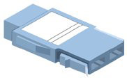
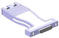
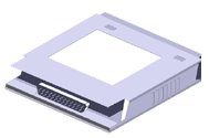
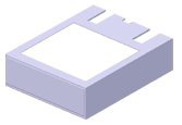
GigaBit Interface Converters (GBICs): These are small interface modules that are used to connect copper or fiber-optic devices to hubs, switches, and HBAs. These devices can be of two types, shortwave connectors and longwave connectors. Shortwave connectors offer connectivity up to 500 meters, whereas longwave connectors can be used to connect devices that are located as far as 10 to 100 kilometers. Figure 1-1-8 displays a GBIC.
-
Gigabit Link Modules (GLMs): These are low-cost connectors that facilitate full-duplex communication between Fibre Channel devices. Like GBICs, GLMs are also of two types, shortwave and longwave. Note that GLMs are available as both external devices as well as internal devices that are built into the HBA. Figure 1-1-9 displays a GLM.
-
Media Interface Adapters (MIAs): These connectivity devices are used to convert copper-based connections into fiber-based connections. Figure 1-1-10 displays an MIA.
-
Transceivers: These connectors are generally used to connect other Fibre Channel devices to switches. 1x9 transceivers, Small Form Factor (SFF) transceivers, and 1x28 transceivers are some of the commonly used Fibre Channel transceivers. Figure 1-1-11 displays a transceiver.
Hubs
The hubs on a storage network are used to implement the ring-like Fibre Channel-Arbitrated Loop (FC-AL) topology. Unlike the hubs used in traditional networks, a typical Fibre Channel hub can support up to 126 nodes.
| Note | The hubs used in traditional networks normally support 4, 8, 12, 16, and 32 ports. Some hubs also offer 64 ports. However, these are expensive devices. |
In addition, Fibre Channel hubs use Port Bypass Circuitry (PBC) that allows devices to be dynamically added or removed from the loop while the loop is still operational. As a result, if you add or remove a device from the loop, you wouldn’t have to manually reconfigure the loop. These hubs automatically reconfigure the entire loop, thus reducing the management load on network administrators.
Fibre Channel hubs that are used on a storage network are of three types, as listed below:
-
Unmanaged hubs: These hubs, as the name suggests, do not have built-in management software. Another important point that you need to remember about unmanaged hubs is that they are not assigned a WWN and a subsequent WWPN when you use them to implement the loop. As a result, they help extend the length of the physical cables and media used on the network. However, they do provide the PBC technology that you read about earlier. Therefore, they can detect an unoperational loop node and reconfigure the loop.
-
Managed hubs: These hubs have built-in management capability, and therefore, they are called managed hubs. These are highly intelligent hubs that can isolate the large amount of traffic, which is generated by the initialization of a loop, from the general traffic. This increases the overall performance of loops. Despite the high intelligence they possess, managed hubs cannot actively participate in protocol-based transactions because they do not support upper-layer protocols.
-
Switched hubs: These hubs are known as "switched hubs" because, just like switches, each individual port of a switched hub is allocated a dedicated bandwidth of 100 Mbps and above, which is not shared by other ports. In addition to the high speed of transactions and performance that they offer, these hubs also actively participate in protocol-based transactions.
| Caution | As stressed earlier, you do not need to use the most expensive devices for your SAN, as they only tend to unnecessarily increase the total cost of implementation of your storage network. For example, you do not always have to implement a switched hub if your organization has a small-sized SAN. You need to thoroughly analyze and understand the business requirements as well as the specification of a device before you actually implement it. |
Bridges and Multiplexers
These Fibre Channel devices allow your storage network and the connected LAN to communicate and thus act as the communication intermediary between Fibre Channel interfaces, such as FICON and ESCON and traditional SCSI interfaces. In addition, Fibre Channel bridges also allow you to integrate legacy SCSI devices seamlessly with a Fibre Channel network. Because of these reasons, bridges are also referred to as Fibre Channel SCSI routers.
The acronym FICON stands for Fibre Interconnection while ESCON stands for Enterprise System Connection. These are proprietary IBM interfaces (protocols) used in Fibre Channel connectivity. FICON is a 100Mbps full-duplex interface, which connects directors to other SAN components. ESCON, on the other hand, is a slower (17Mbps) interface and is used to connect directors to other SAN components in half-duplex mode.
Multiplexers are a special category of bridges, which allow you to interleave signals from multiple devices and transmit them simultaneously through a single transmission medium. Therefore, they can help you in effectively utilizing the available network bandwidth.
Switches
These Fibre Channel devices provide the basic framework for the most efficient topology — the Switched Fabric topology. Typically, they offer 8-16 ports, and a single switch alone allows you to create a small-scale SAN. Like normal switches, they offer a dedicated bandwidth of 100 Mbps and above for each port and thus allow frames to be routed between SAN nodes at high speeds.
Other advanced services provided by Fibre Channel switches are:
-
Buffer-to-buffer flow control during transactions.
-
Services, such as Fabric login and Simple Name Server (SNS). The Fabric Login service allows nodes to be successfully initialized (allocated a unique address) in a switched environment, which enables communication between two nodes. Similarly, the SNS service helps a source node to discover the destination node within the Fabric without causing unnecessary communication overhead.
-
Registered State Change Notification (RSCN) notifies Fibre Channel nodes about the changes in the existing topology.
Depending on the functionality, Fibre Channel switches are divided into three categories. These include:
-
Loop Switches: These switches are comparatively low cost. These are used to connect an FC-AL loop to the rest of the Fabric.
-
Fabric switches: These switches are expensive and are predominantly used to implement the Switched Fabric topology.
-
Directors: This is the most expensive category of switches. This is because they offer the best performance and maximum reliability among all the categories. According to an estimate, the annual downtime for a director is barely five minutes.
Routers and Gateways
Commonly referred to as storage routers, Fibre Channel routers provide an interface among IP-based devices, LANs, and your storage network. In other words, these devices transfer storage data between different networks by using various transmission media and addressing schemes. You'll also find these devices helpful in extending the access of your SAN to the storage devices that are located remotely.
Fibre Channel gateways, like routers, allow you to interconnect networks using different protocols and addressing schemes over a wide area network (WAN). However, they may not have the capability to perform protocol conversion.
Storage Devices
High-performance and high-availability storage infrastructure is the backbone of your storage network. In fact, it is so important that if you fail to choose the right kind of storage infrastructure for your setup, your SAN may fail to live up to your expectations and requirements, regardless of the fact that you have chosen the best switches, routers, bridges, and hubs.
The common SAN storage devices that you'll come across are:
-
Just a Bunch of Disks (JBODs): A JBOD is a loose set of multiple storage disks that act as a single storage entity. Data stored on a JBOD is spanned across multiple disks. As a result, data access is comparatively slow. In addition, the fault-tolerance level and, consequently, the reliability of JBOD is lower than what is expected from a storage system on which several thousand dollars have been invested.
-
Tape libraries: These are inexpensive, high-end storage solutions. They can store anything from 10 GB to several thousand TB of data. In addition, they offer high reliability in transactions. Another benefit that they provide is that most of the vendors offer self-managing tape subsystems. This comparatively low-cost and easy manageability, coupled with the high-reliability factor, makes them an ideal backup medium.
-
Disk storages: These are a set of high-performance and high-availability disks that can save several terabytes of data. An additional benefit that they offer is that they are very reliable storage solutions.
-
Disk arrays: The correct technical term for these storage devices is Redundant Array of Inexpensive Disks (RAID). As the name suggests, these are a set of storage disks that offer high speeds of transactions, high performance, and equally high reliability. The performance of the rest of the disks in the set is not dependent on other disks. As a result, even if one or more disks in the array fail, the device continues to be functional. A single disk array can store up to several terabytes of data. For all these reasons, disk arrays are extremely expensive.
SAN Servers
Most SANs today are heterogeneous in nature. This means that you can mix and match products and solutions from various vendors to arrive at a solution that best suits your organization's requirements and most importantly the allocated budget for your SAN. As a result, a SAN environment may support a wide range of server platforms. This includes widely used platforms such as Linux, Solaris, and Windows.
In addition, even the not-so-widely used platform, such as Macintosh and its various versions, are also supported. Where data cannot be shared between two incompatible server platforms, specialized data conversion applications can be used.
SAN Software
The software aspect of a storage network is invariably associated with the management of the SAN. The basic SAN-related applications include the following broad categories:
-
SAN applications that are used to configure, maintain, and manage the SAN fabric, loop, or the devices connected in a point-to-point manner.
-
SAN applications that help you exploit your expensive storage network and maximize the investment in hardware. These applications generally include the backup/recovery packages and volume managers. Other applications that allow you to perform local or remote mirroring, disk striping, and data replication also belong to the category of network management software.
-
File management applications fall into the third category of SAN management software. These include file-sharing or data-sharing software, extended file systems, and shared file systems.
Cabling
A well-planned and well-implemented cabling system is as important to any network as other building blocks. A SAN might yet again not be up to expectations if you do not have much knowledge about the type of cables that run through the SAN.
SANs use two types of cables to interconnect devices. The first option is copper-based cables that are commonly implemented in traditional networks. Though copper cables still figure in SANlets (a very small SAN) and small-scale SANs, it is the second type of cabling, fiber-optic cables that is used most commonly.
Copper-based Cables
Copper cabling is the time-tested method of interconnecting network nodes. In addition, with the increasing popularity of Gigabit Ethernet, the older copper-based cables have been upgraded to support transfer rates of about 1Gbps.
The copper cables that are commonly used in SANs are of the following two types:
-
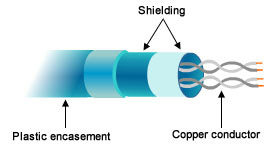
Shielded Twisted Pair (STP): This type of cable comprises bundled pairs shielded by a foil, as shown in Figure 1-1-12. These are moderately expensive cables, which can support data transfer rates within the range of 16 Mbps and 155Mbps. A few vendors also offer STPs that offer transfer rates up to 500Mbps. These cables do not suffer from EMI and other such interferences.
-
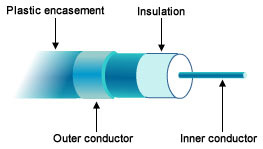
Coaxial: This type of cable comprises two conductors that share a common axis and are separated by an insulating plastic foam, as shown in Figure 1-1-13. The inner conductor can either be a stiff solid copper wire or a wire mesh covered by another insulator. This is a relatively inexpensive category of copper cables that are susceptible to both attenuation as well as EMI. However, it is simpler to implement coaxial cabling as compared to STP-based cabling.
Coaxial cables are popularly referred to as "coax" cables and are available in various specifications. These include the 50 ohm RG-8, RG-11, and RG-58, 75 ohm RG-59, and 93 ohm RG-62 specifications.
The first question that might arise in your mind might be how to connect a Fibre Channel device to a copper cable since both are incompatible. This is where the copper GBICs and MIAs come into the picture. These connectors act as the interface between the Fibre Channel-based SAN devices and copper-based cables.
Despite the advancement in the copper technology and the widespread availability of connectors, interconnecting Fibre Channel devices with underlying copper cables still pose a few problems.
The biggest impediment is that Fibre Channel devices operate at extremely high speeds, whereas the copper cables at a maximum offer a speed of not more than 1Gbps. As a result, the cabling, which ideally should offer you able support for transactions, might end up being a major bottleneck. Other problems that affect the performance of copper cables adversely are:
-
Exposure to Electromagnetic Induction (EMI) and Radio Frequency Interference (RFI), which can instantly bring down the quality of the signal.
-
High rate of signal deterioration (attenuation), if the signal has to traverse long distances.
-
Low bandwidth compared to fiber-optic cabling.
-
Possibility of short-circuits, sparks, and spark-induced fires.
The list of disadvantages of copper-based cabling in a high-performance environment are long, the above-mentioned reasons are the strongest. These reasons have made experts look for an alternative cabling system. The answer to this problem that has emerged over the years is fiber-optic cabling.
Fiber-Optic Cables
Unlike copper-based cables, Fiber-optic cables do not suffer from EMI, RFI, or magnetic fields. They have an extremely low rate of attenuation (practically nil) because light signals do not deteriorate over long distances (remember that sunrays travel over millions of light years to reach you and can still give you a bad case of sunburn). In addition, fiber-optic cables offer very high bandwidths and are absolutely immune to short circuits, sparks, and spark-induced fires.
Another very important point regarding fiber-optic cables is that they can easily provide long-distance connectivity - 10 Kilometers and above. In comparison, most copper cables extend only up to a paltry distance of 30 meters.
Fiber-optic cables are of two types. These are:
-
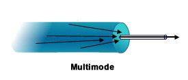
Multimode Fiber (MMF): These cables provide multiple paths for the light signal to travel, as shown in Figure 1-1-14, and allow for connections that can span up to 2 kilometers.
-
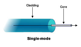
Single-Mode Fiber (SMF): These cables provide a single path for the propagation of a light signal, as shown in Figure 1-1-15. They are used to connect devices that are located over longer distances, spanning up to 10 kilometers.
Fiber-optic cabling in a SAN can be implemented in the following two ways:
-
Jumper cabling: Devices in this cabling system are connected directly to each other using individual jumper cables. As a result, the number of cables in this system is very large. This cabling system works well if the size of the SAN is small. However, in case of large SANs where the number of devices is large, this cabling system fails because the sheer number of cables becomes unmanageable.
-
Structured cabling: Fiber trunk cables, patch panels, and patch cables are used extensively to reduce the number of individual cables in this cabling system. As a result, the number of cables is not large, even if the size of the SAN is large. Therefore, this is an extremely manageable cabling system and is used extensively in medium- to large-sized SANs.

