To improve the performance of a network or a router, you must first analyze the factors that affect the performance. Only then can you apply various methods to improve the network performance. Quality of Service (QoS) is one such mechanism that is adopted to improve the performance of the network or router. QoS refers to the capability of a network to serve network traffic. It also refers to the probability of a data packet successfully passing from one point to another on a network. QoS works on the principle of prioritizing the data packets and transmitting them on the basis of the priority. At the same time, QoS ensures that in assigning this priority, it does not result in the loss of lower priority data packets.
Network traffic can be either ingress or egress. Ingress traffic is the traffic that originates from outside the network’s routers and proceeds towards a destination inside the network. Similarly, traffic that originates inside the network and reaches a destination outside the network through the routers is egress traffic.
This ReferencePoint describes the general concepts of ingress handling, such as sources of delay, queuing, traffic shaping, and traffic policing. It also explains how to implement QoS and describes the process of classification and various methods of traffic shaping and traffic policing. In addition, it describes the DiffServ architecture, which is a QoS mechanism.
Ingress Handling Overview
You can control the flow of data at the ingress to avoid network congestion. For example, an e-mail message that originates outside an enterprise LAN, passes over the Internet, and then enters the enterprise LAN before it is delivered to the recipient. The point where the data enters the enterprise router is the ingress and the flow of data is controlled at this point.
To control the flow of data and improve the performance of the network, you need to understand some concepts of handling data at the ingress, such as sources of delay, buffering and queuing, and bucket models of traffic.
Sources of Delay
Network performance is rated by the time taken to transmit a data packet from the source to the destination. The sources that cause delay in the transmission are:
-
Internal Router Processing Delay
-
Serialization Delay
-
Propagation Delay
-
Forwarding Delay
Internal Router Processing Delay
The processes that take place internally within a router when a data packet reaches the router can cause some delay in transmission. The delays in internal router processing can be attributed to:
-
Convergence-related delays: A router is said to be converged when the Router Information Base (RIB) table is complete and accurate. In large networks, there is a constant change in the RIB and therefore convergence is rarely achieved. Normally, switching modes use small caches to hold the routing information. Therefore, when RIB changes, the switching modes rebuild the entire cache, which increases the load on the processor. This reduces the network performance.
Note The RIB table is the IP routing table on which all packet-routing decisions are based.
-
Performance management delays: All performance management activities, such as classification, marking, shaping, policing, and output scheduling increase the load on the processors, thereby, reducing network performance. For example, classification using access lists and an increase in the number of queues to be serviced result in increased load on the processor.
Serialization Delay
For transmission over the network, the data is clocked onto the medium of transmission at source and clocked off the medium at destination. The transmission medium is usually slower than the router medium. This difference in the speed of the medium results in delay, known as serialization delay. Serialization delay can be defined as the time required to move the bits on and off the medium. Serialization delay is related to link speed and frame length, as shown in the following formula:
Serialization delay = (framelength * 8) / linkspeed in bps
Propagation Delay
Propagation delay is the speed-of-light delay in the medium. It is calculated using the speed of light in a medium depending on the medium being used for transmission. It denotes the time taken for the data clocked onto the medium to move from one end of the link to another.
Propagation delay is related to the length of the link and the type of medium used for data transmission. For example, the propagation delay is approximately 6 microseconds/kilometer of the distance in air between the end-points of the link.
When an electrical or optical signal is placed on a medium for transmission, the energy does not traverse from one end of the medium to the other instantaneously, a delay is induced. The speed of the signal on the electrical or optical interface approaches the speed of light. To reduce the propagation delay, the only variable that can be controlled is the length of the link. To arrive at the amount of delay induced, you can use the following formula:
Delay = Length of the link (meters) / 3.0 * 108 meters/second
In this formula, 3.0 * 108 is the speed of light in vacuum.
To arrive at a more exact propagation delay figure for copper and optical media, use the following formula:
Delay = Length of the link (meters) / 2.1 * 108 meters/second
In this formula, 2.1 * 108 is the speed of light over a copper or optical media.
For example, if the length of a link between two routers R1 and R2 is 1000 kilometers, then the propagation delay for this link can be calculated as:
1000 * 1000 / 3.0 * 108
The propagation delay in this case is 0.048 ms.
Forwarding Delay
Forwarding delay refers to the time taken by a router or a LAN switch to examine the data packet that arrives at the ingress and place that data packet in the output queue at the egress for transmission. The forwarding delay is also affected by the forwarding logic used by the router or LAN switch. The two forwarding logics are:
-
Store and forward: The router or the LAN switch waits for all the data packets of a frame to arrive at the ingress, before forwarding the entire frame to the egress.
-
Cut-through or fragment-free: The router or the LAN switch forwards the data packets to the egress as they arrive at the ingress, without waiting for the entire frame to arrive.
However, forwarding delay is typically a small component that can be ignored when calculating the overall delay.
Queuing
Queuing refers to holding the data packets in buffers when network congestion occurs and the transmission line is not able to transmit all the data packets.
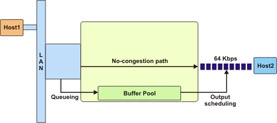
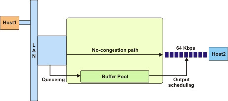
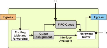
The data transmission continues smoothly as long as the amount of data to be transmitted is less than or equal to the network capacity. If the data to be transmitted is greater than the network capacity, it results in network congestion. Network congestion can also lead to data loss. To prevent data loss during congestion, the excess data packets can be placed in a buffer, as shown in Figure 7-1-1, until the network traffic congestion is eased off:
For example, consider a situation where multiple hosts are using the same link to transmit data to the destination. In this situation, further assume that the link is busy transmitting a data packet from Host1 and at the same time, a data packet from Host2 arrives at the ingress. The link can transmit the data packet from Host2 only after completing the transmission of data packet from Host1 and may result in loss of the data packet from Host2. To avoid loss of the data packet, the data packet from Host2 can be placed in a buffer until the link completes transmission of the data packet from Host1.
In a different situation, assume that there is less load on the network, but some Voice over Internet Protocol (VoIP) data packets need to be transmitted. The VoIP protocol is tolerant to loss of data but not delay. In this situation, you can prioritize the VoIP data packets and queue the other non-VoIP data packets.
During buffering or queuing, the following two algorithms are used:
-
Queuing algorithm: Specifies when the data packets are placed in a queue and the queue in which each data packet is to be placed.
-
Scheduling algorithm: Specifies when the queued data packets will be transmitted and from which queue the data packets will be sent in case of multiple queues.
In queuing, if the buffer overflows with the data packets arriving from multiple hosts, the router drops the latest data packets. The dropping of the latest data packets from the queue is known as tail drop.
Queuing also introduces delay. Queuing delay refers to the amount of time the data packets are held in a queue before being transmitted.
Important Terms
Table 7-1-1 describes some of the important terms related to ingress handling:
Principles of QoS
The goal of QoS is to help manage the performance of the network or router by providing better service to certain data packets as compared to other data packets. To achieve this goal, the priority of the required data packets is increased or reduced. To set the priority of the data packets, you first need to identify the data packets that are to be given preference. The classification process helps identify the high-preference data packets. After identifying the required data, you can perform one of the following actions:
-
Connection admission control: Limit the number of hosts connecting to the router at the same time.
-
Shaping: Limit the bandwidth for the preferred data to avoid overflow of data and buffer the excess data for transmission later.
-
Policing: Limit the bandwidth for the preferred data to avoid overflow of data and drop the excess data.
The Classification Process
The classification process helps identify the high-priority data packets. These data packets are identified based on the match criteria specified in access lists or maps. Access Control Lists (ACLs) or maps are used for filtering the data packets as a firewall and for selecting types of traffic to be analyzed or forwarded. Access lists test only for one condition and specify only one action. On the other hand, maps test for multiple conditions and specify multiple actions.
The classification process uses the class and policy maps. A class map specifies various criteria for classifying the data packets. A policy map specifies what action must be performed on various types of data packets.
When a data packet matches a criterion, one of the following actions is performed:
-
The data packet is dropped.
-
The data packet is queued for transmission.
-
The data packet is marked so that the subsequent processes and routers identify the data packet and take action accordingly.
Configuring Class Maps
A class map defines the criteria for classifying the data packets. The first step in the classification process is to recognize all the data packets that belong to a class or category. This recognition of data packets can be achieved using either access lists or match commands of class maps. To configure a class map for classification of packets, you can use the class-map function, using the syntax:
class-map
Table 7-1-2 lists the class-map variant values:
| Class-map Variant | Description |
|---|---|
| name or match-all name | Specifies that the data packet must match all the criteria defined in the map. |
| match-any name | Specifies that the data packet must match one or more criteria defined in the map. |
After specifying the class-map variant to use, you must code match commands. The class map contains match commands that define the criteria against which each data packet is matched. Depending on the match command that the data packet matches with, the data packet is classified. Table 7-1-3 describes the various match commands:
| Match Command | Description |
|---|---|
| access-group number | Specifies that the data packet must match the access list number. |
| Any | Specifies that all the data packets match the criteria. |
| class-map name | Specifies that the data packet must match the class map nested within this class map. |
| cos cos-number | Specifies that the data packet must match the specified class of service value, cos-value. |
| destination-address mac mac-address | Specifies that the mac address of the destination of the data packet must match the specified mac-address. |
| input-interface interface-name | Specifies that the ingress interface of the data packet must match the specified interface-name. |
| ip precedence precedence-value | Specifies that the IP precedence of the data packet must match the specified precedence-value. |
| ip rtp starting-port port-range | Specifies that the RTP port of the data packet must match the specified starting-port port-range. |
| not match-criteria | Specifies that the data packet must not match the specified match-criteria. |
| protocol protocol | Specifies that the data packet must be transmitted using the specified protocol. |
| qos-group index | Specifies that the qos group number of the data packet must match the specified index. |
| source-address mac mac-address | Specifies that the mac address of the source of the data packet must match the specified mac-address. |
Configuring Policy Maps
Policy maps define the action to be performed on each category of data packets. The class maps only classify the data packets, they do not perform any action on the data packets. The policy map associated with the class map act on the data packets. Some of the actions that a policy map specifies are drop the data packet or queue the data packet. To configure a policy map, you must perform the following steps:
-
Associate a policy map with a class map.
-
Add policy statements that specify the action to be performed on each category or class.
The following command associates a class with a policy map:
service-policy policy-name
The policy statements begin with the following command:
Policy-Map name
Table 7-1-4 describes various parameters that can be used with the Policy-Map statement:
| Parameter | Description |
|---|---|
| class class-name | Specifies the class with which the policy map is associated. |
| bandwidth | Specifies the amount of bandwidth, in terms of kbps or percent of the total bandwidth allocated to the class. |
| Queue-limit number-of-packets | Specifies the maximum number of data packets that can be queued for the class. |
How Class Maps and Policy Maps Work
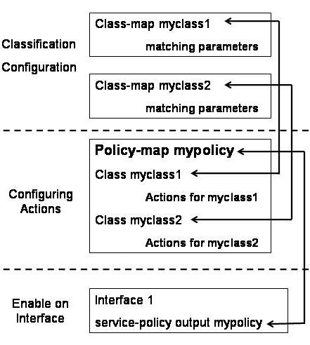
The class maps define various categories of data and use match commands to specify the criteria to categorize data packets. The policy maps specify the action that needs to be performed on each category of data packets. A single policy map can refer to multiple class maps. The interface is configured to refer to the policy map, which in turn refers to the class maps. Figure 7-1-2 shows how policy maps and class maps work:
In the above figure, two classes, myclass1 and myclass2, have been configured to classify the data packets into two classes. These classes contain some match commands that identify the data packets and classify them. The actions to be performed on the two classes are defined in the mypolicy policy map. After creating the policy map, you can configure the policy map to reference multiple classes.
The mypolicy policy map references two classes, myclass1 and myclass2. Under the reference to each class, some action commands have been specified. The action commands define the action to be performed on the data packet in each class. You can define different action commands for various classes. After the class maps and policy maps are configured, you can use the service-policy command to enable QoS on the interface. The service-policy command specifies the policy map to be used on the interface.
Traffic Policing
The traffic policing mechanisms specify the rules for dropping data packets or marking the data-packets that can be dropped. Various traffic policing mechanisms include: First-In First-Out (FIFO), Weighted Fair Queuing (WFQ), Class-Based Queuing (CBQ), Custom Queuing (CQ), Priority Queuing (PQ), Committed Access Rate (CAR), Random Early Detection (RED), and Weighed Random Early Detection (WRED).
First-in First-out
FIFO is a simple queuing process intended to convert bursts of input to a smooth output. FIFO works on the basic principle that all traffic is equally important. As the name suggests, FIFO queues the data packets in the order they arrive at the ingress, as shown in Figure 7-1-3:
FIFO does not require classification or scheduling because it involves only one queue. You can configure the length of the FIFO queue based on your requirements. If you configure a long FIFO queue, it can hold large number of data packets and is most unlikely to fill. A long queue reduces the number of data packets being dropped. However, it induces a long queuing delay. On the contrary, if you configure a short queue, the queuing delay will be reduced. However, the queue is likely to be filled up quickly, resulting in more data packets being dropped from the queue.
The FIFO method does not work well with all protocols because various protocols have different flow control requirements. For example, VoIP data is transmitted in small data packets over the network so that there is no delay in the data packet reaching the destination. However, FIFO cannot distinguish between various types of data packets. As a result, the VoIP data packets are queued and transmitted later, resulting in a disrupted voice output.
To overcome the problem with FIFO, you can:
-
Send data in smaller packets over the network, irrespective of the type of data.
-
Prioritize the data packets on the basis of the type of data.
Priority Queuing
PQ is the best option to transmit data that must reach the destination. PQ creates four queues ranging from high-priority to low priority— high, medium, normal, and low. During network congestion, PQ places the incoming data packets in one of these four queues using pre-defined filters. These filters can be defined based on specified ACLs, the incoming interface, length of the data packet, and TCP/UDP port numbers. If a particular queue is full, the data packet is dropped.
Before transmitting any data packet, PQ checks whether the high-priority queue is holding any data packet. If yes, PQ sends the data packets in the high-priority queues in a first-in first-out manner. After the high-priority queue is empty, PQ services the other queues in order of their priority.
Each queue has a limited capacity to hold data packets. Table 7-1-5 lists the number of data slots assigned to each queue:
| Queue | Number of data slots |
|---|---|
| High | 20 |
| Medium | 40 |
| Normal | 60 |
| Low | 80 |
Any excess data packets in any of the queues are dropped, they are not placed in any other queues although data slots are available in those queues. For example, if all the 20 data slots in the high-priority queue are filled, the twenty-first packet that arrives at the high-priority queue will be dropped. This packet cannot be placed in the medium-, normal-, or low-priority queues.
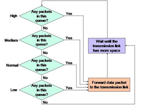
The most distinctive feature of priority queuing is its scheduler. The scheduler services the queues by sending the queued data packets to the transmission link. The logic that the scheduler follows when serving the four priority queues is shown in Figure 7-1-4:
Figure 7-1-4 shows that if the high-priority queue has a data packet waiting, the scheduler will send the data packets from the high-priority queue. If the high-priority queue is empty, the scheduler sends one data packet from the medium-priority queue for transmission. Then, the scheduler again checks the high-priority queue for data packets. The scheduler services the normal-priority queue only after the high- and medium-priority queues are empty. Similarly, the low-priority queue is serviced only when all the other three queues are empty.
The advantage of PQ is that high-priority data packets are transmitted with minimal delay. However, its disadvantage is that it induces long delays in transmission of the data packets in the low-priority queue. The situation is worse during network congestions because the data packets in the low-priority queue are serviced after delays longer than those that occur during normal conditions. This extended delay can cause an application to stop responding because its data packets have not been transmitted.
The data packets can be assigned to various queues using access lists. These access lists classify the data packets based on protocol family or specific interface. The list-number parameter of the priority-list subcommand specifies the priority list in the range of 1 to 16. The priority-list subcommand to classify data packets based on the protocol family is shown in the following syntax:
priority-list
list-number protocol protocol-name
{high | medium | normal | low}
queue-keyword keyword-value
Table 7-1-6 describes the various queue-keyword values:
| Keyword | Description |
|---|---|
| Fragments | Specifies that the rule must be applied to all fragments of a fragmented IP packet. |
| lt | gt | Specifies that the rule must be applied to packets having a length less than (lt) or greater than (gt) the specified value. |
| tcp | udp | Specifies that the rule must be applied to packets whose TCP or UDP port number is the specified value. |
| List | Specifies an access list that is valid for that particular protocol. |
The priority-list command to classify data packets based on specific interface is shown in the following syntax:
priority-list
list-number interface interface-type
interface-number {high | medium | normal | low}
Custom Queuing
CQ overcomes the biggest drawback of PQ. CQ services all the queues one after another in a round-robin manner, so that the data packets in each queue get equal service.
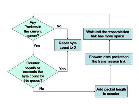
CQ involves multiple queues. The first queue (queue 0) is always allocated to the system traffic. You can define a maximum of sixteen queues excluding the queue 0. Each one of the sixteen queues will have different classification criteria. As in the case of PQ, the scheduler is the most important feature of CQ. The scheduler cycles through all the queues one after another. It sends a pre-determined number of bytes of data from the first queue before servicing the second queue. Then, it sends the pre-determined number of bytes of data from the second queue and moves on to service the third queue. If a queue is empty, CQ skips that queue and services the next queue. The logic that the CQ scheduler uses to service various queues is shown in Figure 7-1-5:
You can define the number of bytes that CQ must send from one queue before proceeding to the next queue. Alternately, you can specify the number of data packets that must be sent from each queue in one cycle. CQ does not divide the available bandwidth among the configured queues. The percentage of bandwidth allocated to a queue depends on the maximum number of bytes that will be transmitted during one cycle. For example, if you configure 5 queues and specify the byte count for each queue as 10000 bytes, the percentage bandwidth assigned to each queue can be calculated using the following formula:
10000 / 50000 = 0.2 or 20%
In this case, each queue has been allocated 20% of the total available bandwidth. Assuming that for one cycle, the fourth queue does not have any data packets to be transmitted, the bandwidth allocated to the fifth queue will be 40%. The bandwidth allocation for queues 1 to 5 for that cycle will be 20%, 20%, 20%, 0%, and 40% respectively. Because the fourth row is empty, the sum of the total byte count for all queues will be 40000 bytes. The queues 1 to 3 will be serviced at 20% bandwidth as earlier. This is because the scheduler does not know that queue 4 is empty. After the scheduler knows that queue 4 is empty, it allocates the percent bandwidth allocated to queue 4 to queue 5.
It is not necessary that you must assign the same byte count for each queue. The byte count can vary depending on the type of data to be serviced. The total bandwidth allocated to any queue, queue x, can be calculated using the following formula:
The byte count of queue x / sum of the byte counts for all queues
CQ does not name the queues as in case of PQ. Instead, CQ numbers the queues from 1 to 16. The default queue length is 20. You can set the queue length to zero, which means that the queue has an infinite length. Inside each queue, CQ follows the FIFO logic to service the data packets.
The biggest drawback of CQ is that it does not have the option of servicing only one queue that holds high-priority data packets as in case of PQ. As a result, CQ cannot provide good service to delay-sensitive data packets. The other drawback of CQ is that neither the length of a queue nor the size of the packets in the queue can be determined.
Weighted Fair Queuing
WFQ works on the principle that interactive applications transmit smaller data packets as compared to non-interactive applications, which send voluminous data packets. WFQ uses an algorithm to segregate low-volume and high-volume data packets into two separate queues, as shown in Figure 7-1-6:
In the above figure, WFQ prioritizes the queue holding the low-volume data packets over the queue that holds the high-volume data packets queue. The data packets in the high-priority queue are transmitted first. After the high-priority queue is empty, one data packet from the low-priority queue is transmitted. WFQ then checks the high-priority queue for any new data packets. If data packets exist in the high-priority queue, these data packets are transmitted, until the high-priority queue is once again empty.
WFQ overcomes the drawbacks of FIFO with respect to applications requiring low-latency. The only problem with WFQ is that there exists a queue, which holds the network control data and has a priority higher than the high-priority queue defined by WFQ.
WFQ also differs from PQ and CQ in the following ways:
-
WFQ does not allow you to define classification categories. Instead, WFQ classifies each data packet based on flows. All the data packets that have the same source and destination IP address and port numbers are included in one flow.
-
WFQ does not support a scheduler.
-
WFQ supports a very large number of queues – a maximum of 4096 queues on each interface.
-
WFQ uses a tail drop scheme, which is a modified version of the tail drop scheme used in PQ and CQ.
Class-based Weighted Fair Queuing
CBWFQ combines the principle used in WFQ and CQ. CBWFQ helps you create queues to hold various data packets as in CQ and prioritize the queues as in WFQ. As in CQ, CBWFQ reserves bandwidth for every queue. The difference is that in CBWFQ you can configure the percent bandwidth for each queue instead of specifying the byte count. CBWFQ can also use WFQ within each queue except that it does not keep up for all the network traffic. In addition, CBWFQ allows you to define the maximum length that a queue can grow to or the maximum number of data packets each queue can hold at any time.
To configure CBWFQ, you first create a class map to identify and classify the data packets into their respective queues. You then create a policy map to define how the queues must be handled. Finally, you assign traffic policies to various interfaces.
CBWFQ supports a maximum of 64 queues. The default length of a CBWFQ queue is 64 bytes. You can configure 63 queues depending on the classification categories you define. One queue is configured automatically and is known as the class-default queue. If any of the data packets arriving at the ingress does not match any classification defined for all the 63 queues, it is placed into the class-default queue. However, you can change the configuration details of the class-default queue.
CBWFQ follows the WFQ logic in the class-default queue. This logic enables CBWFQ to handle low-volume interactive data effectively. When configuring CBWFQ, you must remember to allocate the right amount of bandwidth for the class-default queue. CBWFQ is considered to be a powerful queuing tool because of its capability of allocating bandwidth to all the queues and then allocating the rest of the available bandwidth to WFQ in the class-default queue.
Committed Access Rate
CAR supports a classifying function by which you can have additional policing actions other than forwarding or dropping data packets. You can use CAR for traffic policing when you need to ensure maximum bandwidth for the network traffic. The syntax of the basic CAR command is:
rate-limit {input | output}
bps burst-normal burst-max
conform-action action
exceed-action action
In the above syntax:
-
bps denotes the committed information rate.
-
burst-normal denotes the committed burst size.
-
burst-max denotes the excess burst size.
-
conform-action action denotes the action that is triggered when the burst rate is within the CIR.
-
exceed-action action denotes the action that is triggered when the burst rate is within the CBR.
Under the same interface, you can specify multiple rate-limit commands.
Table 7-1-7 describes the conform- and exceed- actions values:
| Action | Description |
|---|---|
| continue | Evaluates the next rate-limit command. |
| drop | Drops the data packet. |
| set-prec-continue new-precedence | Sets the IP precedence to the specified new-precedence and evaluates the next rate-limit command. |
| set-prec-transmit new-precedence | Sets the IP precedence to the specified new-precedence and transmits the data packet. |
| transmit | Transmits the data packet. |
Random Early Detection
RED involves a single queue of data packets. It analyzes the trend of the queue growth by monitoring the length of the queue. When monitoring the length of the queue, RED keeps track of the number of data packets in the queue and the rate at which the data packets arrive and leave the queue.
As long as the queue has enough capacity to handle the data packets, RED does not act. If the number of data packets in the queue reaches a critical limit, RED does not allow any new packets to be added to the queue, until the capacity of the queue comes within acceptable limits. To bring the capacity of the queue back to acceptable limits, RED randomly drops data packets from the queue. If the randomly-dropped data packet is a TCP packet, the packet can be retransmitted, whereas if the randomly-dropped data packet is a UDP packet, the packet is lost, which is acceptable to most of the UDP applications. As the name suggests, Random Early Detection or RED detects queue congestion early, thereby reducing tail drops.
The logic that RED follows contains the following two parts:
-
RED must detect when congestion occurs or under what conditions it must discard packets.
-
If RED decides to drop packets, it must decide how many packets to drop.
In this logic, when a queue is reaching a critical limit, RED first measures the average queue depth. Based on the average queue depth, RED decides whether congestion is occurring. If congestion is occurring, RED decides whether to discard packets and how many packets to discard.
TCP data benefits the most from RED. This is because if RED drops a TCP data packet from the queue, TCP assumes that the packet was dropped due to heavy network traffic. Therefore, TCP starts transmitting the data packets slowly.
Weighted Random Early Detection
WRED is the same as RED except that WRED sets preferences among the data packets based on IP precedence or IP Differentiated Services Code Point (DSCP) values. WRED also maintains multiple queues. When network congestion occurs, WRED starts dropping data packets from the least preferred queue until the network traffic eases.
WRED can be enabled on any interface but cannot be enabled on interfaces that are already using any other queuing mechanism.
The WFQ logic first calculates the average queue depth. It then compares the average queue depth with the minimum and maximum thresholds to decide whether it must discard data packets. If the average queue depth is between the minimum and maximum thresholds, WRED discards a certain percentage of data packets. If the average queue depth exceeds the maximum threshold, WRED discards all new packets. WRED sets the minimum and maximum thresholds based on IP precedence or DSCP value of the data packets. However, the average queue depth is calculated for all the data packets in a queue regardless of the IP precedence or DSCP value of the data packets.
Table 7-1-8 lists the commands used to configure WRED:
| Command | Description |
|---|---|
| random-detect [dscp-based | prec-based] | Used when configuring an interface or a class. It enables WRED specifying whether WRED should react to IP Precedence or DSCP value of the data packets. |
| random-detect [attach group-name] | Used when configuring an interface. It enables WRED on interfaces referred by the specified group-name. |
| random-detect-group group-name [dscp-based | prec-based] | Used for global configuration on all interfaces. It groups WRED parameters that can be enabled on the interfaces using the random-detect attach command. |
| random-detect precedence precedence min-threshold max-threshold mark-prob-denominator | Used when configuring an interface, a class, or a random-detect-group. It overrides the default settings for the specified precedence to set the minimum and maximum WRED thresholds and for percentage of packets discarded. |
| random-detect dscp dscpvalue min-threshold max-threshold mark-prob-denominator | Used when configuring an interface, a class, or a random-detect-group. It overrides the default settings for the specified dscpvalue to set the minimum and maximum WRED thresholds and for percentage of packets discarded. |
| Random-detect exponential-weighting-constant exponent | Used when configuring an interface, a class, or a random-detect-group. It overrides the default settings for the specified exponential weighting constant. Lower values for exponent makes WRED reach quickly to the changes in the queue depth. On the contrary, higher values for exponent makes WRED react slow to the queue depth changes. |
Traffic Shaping
Traffic shaping is a process in which you allow the high-priority data to pass through the network immediately, while delaying the transmission of low-priority data. Various traffic-shaping techniques include: Generic Traffic Shaping (GTS), Distributed Traffic Shaping (DTS), and Frame Relay Traffic Shaping (FRTS).
Generic Traffic Shaping
GTS was the first traffic shaping technique introduced by Cisco. You can enable GTS using the following subcommand on any interface of a router:
traffic-shape rate
bit-rate
[burst-size [excess-burst-size]]
You can also limit GTS for the traffic from a specific IP access-list so that only a specific category of data packets will be classified for traffic shaping and not all the data on that interface. To do so, use the following command:
traffic-shape group access-list-number
bit-rate
[burst-size [excess-burst-size]]
When using GTS on Frame Relay, you can specify a minimum bit-rate for traffic to be shaped. When you do so, shaping is not applied to any data packet with a bit-rate less than the specified bit-rate. You can specify the minimum bit-rate using the following command:
traffic-shape adaptive minimum-applicable-bit-rate
Using GTS, you can also adjust the bit-rate on the router based on Forward Explicit Congestion Notifications (FECNs) and send Backwards Explicit Congestion Notifications (BECNs) back to the source. The BECNs will try to trigger the congestion control of the router.
Distributed Traffic Shaping
Many enterprise and service provider customers need to shape traffic in their networks and, sometimes, shape IP traffic independent of the underlying interface. In other cases, traffic needs to be shaped to ensure adherence to committed information rates on Frame Relay links. DTS is used to manage the bandwidth of an interface to avoid congestion, to meet remote site requirements, and to conform to a service rate that is provided on that interface.
DTS uses queues to buffer traffic surges that can congest a network. Data is buffered and then sent into the network at a regulated rate. This ensures that traffic will behave according to the configured descriptor, as defined by Command Information Rate (CIR), Committed Burst (Bc), and Excess Burst (Be). With the defined average bit rate and burst size that is acceptable on that shaped entity, you can derive a time interval value.
Be allows more than Bc to be sent during a time interval under certain conditions. Therefore, DTS provides two types of shape commands, average and peak. When shape average is configured, the interface sends no more than the Bc for each interval, achieving an average rate no higher than the CIR. When shape peak is configured, the interface sends Bc and Be bits in each interval.
In a link layer network such as Frame Relay, the network sends messages with the FECN or BECN if there is congestion. With the DTS feature, the traffic shaping adaptive mode takes advantage of these signals and adjusts the traffic descriptors. This approximates the rate to the available bandwidth along the path.
Frame Relay Traffic Shaping
You must use the Map-Class commands to configure FRTS. The FRTS configuration begins with the following command:
Map-Class frame-relay Map-Class-name
You can configure various parameters under the Map-Class entry. Table 7-1-9 lists various Map-Class parameters that can be used for FRTS:
| Parameter | Description |
|---|---|
| custom-queue-list number | Specifies the number of a custom queue list that must be used for the map class. |
| priority-group number | Specifies the number of a priority list that must be used for the map class. |
| cir out bps | Specifies the outbound CIR. |
| mincir [in | out] bps | Specifies the minimum acceptable CIR for input (in) or output (out). If neither in nor out is specified, the specified CIR will be used both for input and output. |
| bc out bits | Specifies the size of the outgoing committed burst in bits. |
| be out bits | Specifies the outgoing excess burst size in bits. |
| Note | All the map class parameters described in the above table must be prefixed with "frame-relay". |
The DiffServ Architecture - A QoS Mechanism
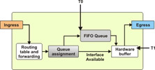
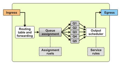
To ensure smooth performance of the network, it is essential to define and control the network traffic. You must identify the amount of traffic expected on the network. If the expected load exceeds the network capacity, the level of network performance reduces. To improve the network performance, you need to assign additional resources to the network. For this, you need to define the desired performance level and the network load for which this performance level is expected. To analyze the network load, classify all the applications running on the network into various categories ranging from applications that require high performance, such as real-time applications, to applications that work well on low performance also, as shown in Figure 7-1-7:
By classifying the applications, you are placing data packets in queues for transmission or dropping the excess data packets. After classifying the applications, you can schedule the load on the network. By scheduling the load on the network, you are periodically emptying the queues.
DiffServ creates a set of classes and specifies the priority for dropping data packets from the queue within each class. It extends the semantics of the Type of Service (ToS) byte of the IP header of the data packets to specify drop criteria.
Generally, a ToS byte is divided into two parts, 3 bits for specifying the IP precedence and 4 bits for specifying the type of service. However, all QoS mechanisms do not consider IP precedence. Therefore, DiffServ modifies the ToS, byte as shown in Figure 7-1-8:
DiffServ uses the 3 bits allocated for IP precedence along with the next 3 bits of the ToS byte to create four classes and assign three drop probabilities to each class. The last two bits of the ToS byte are used for Early Congestion Notification (ECN).

