Introduction
Currently, most companies have a networking environment where storage space is directly attached to a server or scattered over a large number of servers. If a server has less disk space available, an IT administrator can simply add an additional hard disk. This is an inexpensive way of handling storage problems. However, such an approach can lead to storage management and administration difficulties. Scalability, accessibility, and performance are some of the other issues that also need to be addressed.
With massive increase in volumes of information, many companies have started facing problems associated with data storage and management. One solution is Storage Area Networks (SANs) that allow you to manage storage needs proactively while ensuring performance and accessibility. A SAN provides the infrastructure to establish connections between storage devices and servers, allowing servers or end users to share storage devices. This can simplify storage management.
Historically, SANs have been based on the Fibre Channel technology that has been criticized for being costly and difficult to implement.
Because Fibre Channel SANs are not IP-based, they are implemented as stand-alone networks. To overcome this problem, Internet technologies have been put to use to create SAN-to-SAN connectivity. Organizations can scale from the scope of a LAN to a WAN by establishing IP SANs. In addition, an IP SAN leverages new networking developments on the Internet, such as Quality of Service (QoS) and security.
Internet Small Computer System Interface (iSCSI) has emerged as the leading protocol standard for IP storage. It is one of the IP storage protocols that solves the problem of SAN connectivity.
This ReferencePoint provides you with an overview of the concepts related to iSCSI and the factors contributing to its emergence as a competitor to Fibre Channels. The ReferencePoint also provides an overview of SAN and IP storage.
Storage Area Network
A Storage Area Network (SAN) is a high-speed network that connects servers to storage elements. A SAN is part of the overall network of an enterprise and its purpose is to transfer data among servers and storage devices.
SAN consists of a management layer that organizes physical connections, storage elements, and servers so that data transfer is secure and error free. You can implement a SAN using various technologies, such as Fibre Channel, Enterprise Systems Connection (ESCON), Serial Storage Architecture (SSA), and IP.
A SAN is a high-speed network designed specifically for information management. It provides flexibility by segregating information management from information processing. A SAN ensures improved performance because storage traffic is offloaded from a LAN to a network dedicated to storage traffic. This high-speed network increases the bandwidth by reducing the amount of network traffic transmitted along corporate networks. A SAN provides an infrastructure where servers at different locations have direct access to shared storage resources.
A SAN also enables management activities, such as backup, archiving, and recovery, to take place independent of any server and LAN. With a separate information management network, additional capacity can be added, as required, with minimum effect on the performance of application servers, transaction servers, LANs, or WANs. A SAN simplifies data management by enabling the use of a common set of tools and a single point of control. It also provides a centralized, shared storage pool for various platforms.
Fibre Channel SAN
Fibre Channel is a communication protocol. It is a high-speed transmission technology that can be used as a front-end communication network, a back-end storage network, or both simultaneously. However, Fibre Channel has emerged as a high-speed transport technology used to build SANs.
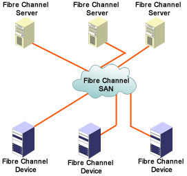
Fibre Channel is used in SAN for connecting multiple hosts to dedicated storage systems, as shown in Figure 4-1-1.
Using Fibre Channel, hosts not only transfer data to a storage system through SCSI but also transfer data to each other through the same IP network. Fibre Channel supports the existing peripheral interfaces and communication protocols, including Fiber Distributed Data Interface (FDDI), High-Performance Parallel Interface (HiPPI), IP, SCSI-3, and Ethernet. However, Fibre Channel has been primarily used for transmitting SCSI traffic from servers to disk arrays.
Fibre Channel has functioned as the primary means for building SANs because of its high performance, connectivity, and ability to support block-oriented storage protocols. Fibre Channel can attach devices by using a number of methods, such as dual and single loops, hubs, and switches.
Limitations of a Fibre Channel SAN
Although the Fibre Channel technology has been widely adopted for building SANs, it has a number of limitations. One limitation is that a Fibre Channel SAN requires a separate network setup. It also requires a separate set of fiber and switches, which are expensive.
Another limitation of Fibre Channel is that it can cover a distance up to a range of 12.4 miles. A Fibre Channel extension can be used to extend a SAN to a WAN. However, a simple Fibre Channel extension cannot enable companies, such as service providers, to implement multiple, interconnected SANs for providing storage space at a global level.
In addition, a Fibre Channel extension is a costly, inflexible, and difficult-to-manage technology. This is because a Fibre Channel extension requires a dedicated physical connection or a logical connection among SANs. In addition, a Fibre Channel extension provides a SAN-to-SAN connection instead of a device-to-device connection.
On the horizon are new solutions aimed at solving the limitations of Fibre Channel. Some of the probable storage solutions are iSCSI, Fibre Channel over IP (FCIP), Internet Fibre Channel Protocol (iFCP), and, in the near future, InfiniBand.
IP Storage
IP storage is a networking technology that connects clients or servers to storage elements through IP. The IP storage protocols allow block-level storage data to be transmitted over an IP-based network by using the standard TCP.
Because the cost of managing and administering SANs as isolated networks is high and the availability of qualified technical talent for managing SANs is low, many companies have switched to IP storage.
Another reason for the switch to IP storage is that it enables you to tie together all available storage networks. SANs ensure that a server can access all data. However, isolated SANs are not accessible by other storage networks. Isolated SANs are also not able to fully utilize the cost effective services provided by Storage Service Providers (SSPs).
IP-based storage is becoming popular because IP has gained worldwide acceptance, which gives it various advantages over other networking protocols. One of the advantages is the availability of a large pool of qualified technical talent with IP experience. There is also a large development base for IP because it is being used as a general-purpose networking protocol. In addition, a wide variety of quality services and security protocols already exist for IP. IP is also relatively inexpensive and runs on virtually any subnetworking technology, such as Ethernet.
Benefits of IP Storage
IP is used as a single networking technology for both LAN and SAN because IP is cheaper to adopt, deploy, and maintain than Fibre Channel.
IP-based storage networks provide many benefits. IP storage utilizes the existing IP network infrastructure, expertise, and services to build high performance SANs. IP storage is vendor-independent so that it can be used to connect two or more networks. In addition, it reduces expenditure on training and recruiting new staff. This is because IP, which forms the basis of IP storage, is a commonly used networking technology.
IP storage is more reliable because it is built on a proven transport infrastructure. It also enables you to move from 1 Gigabit Ethernet to 10 Gigabit Ethernet and beyond. In addition, IP storage enables the establishment of networks across continents and across data centers. This scalability over long distances enables remote data replication and disaster recovery. IP storage also facilitates common sourcing and maintenance of networking equipment.
These benefits make IP storage useful for:
-
Service providers using IP and Ethernet
-
Organizations that require storage connectivity and incremental scaling of their storage infrastructure
-
Organizations that need to send storage traffic over MAN or WAN
-
Organizations that want to connect the existing Fibre Channel SANs or Fibre Channel devices and use IP networks
-
Organizations that need highly scalable network technology
-
Organizations that need both local and extended IP connectivity
IP Storage Protocols
Internet Engineer Task Force (IETF) is currently developing the following IP storage protocols:
-
iSCSI
-
FCIP
-
iFCP
Each of these protocols has various advantages and disadvantages, which you should consider while selecting an IP storage protocol. You should also consider the timing of its requirement, the existing base of SAN equipment and software, and the network administration cost model.
Internet Small Computer System Interface
iSCSI is a TCP/IP-based protocol for establishing and managing connections between storage devices, hosts, and clients. The storage devices are connected through an IP network instead of a direct SCSI-compatible cable. iSCSI encapsulates SCSI commands on an IP network. iSCSI facilitates data transfer over intranets and manages storage over long distances.
The potential benefit of iSCSI is that you can connect to remote storage devices to replicate data without investing time and money on developing new software. Due to the widespread use of IP networks, iSCSI can be used to transmit data over LAN, WAN, or the Internet and to enable location-independent data storage and retrieval.
Fibre Channel over IP
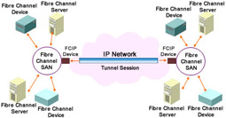
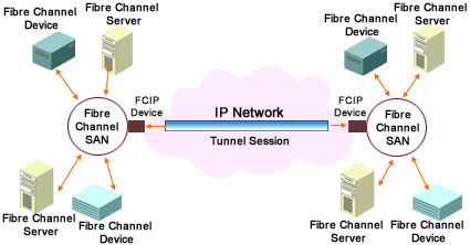
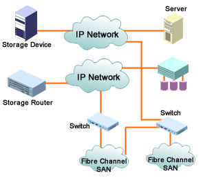
Fibre Channel over IP (FCIP) is a point-to-point tunneling protocol used to connect Fibre Channel SANs that are geographically distributed. As shown in Figure 4-1-2, FCIP connects isolated Fibre Channel SANs over IP networks.
The FCIP technology makes data available from several sites simultaneously. For instance, a Fibre Channel SAN located in Detroit might share data with another SAN located in Los Angeles so that users in both cities have access to the same information at the same time. FCIP also provides data protection. For instance, a Fibre Channel SAN located in Manhattan can be connected to another Fibre Channel SAN located in Brooklyn to replicate data for disaster recovery purposes.
| Note | Tunneling is a technology that encapsulates the protocol of a network inside the protocol of another network and uses the facilities of the second protocol to transfer data. Tunneling is also known as encapsulation. |
In a FCIP network, Fibre Channel data is tunneled through the IP network from a SAN at one location to a SAN at another location. FCIP first encapsulates the Fibre Channel frames, which contain the SCSI protocol, over TCP/IP links. Next, the encapsulated Fibre Channel frames are unwrapped at the other end of the IP connection by FCIP.
The FCIP technology is an ideal IP storage solution for companies that have a large base of Fibre Channel. It is also an ideal solution for companies that want to continue using Fibre Channel for high data throughput instead of shifting to high-speed Ethernet networks.
Internet Fibre Channel Protocol
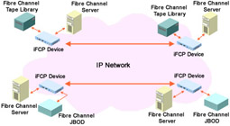
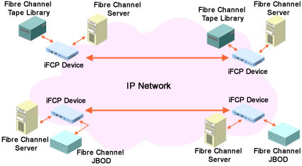
Internet Fibre Channel Protocol (iFCP) is a gateway-to-gateway protocol used for interconnecting Fibre Channel storage devices or Fibre Channel SANs. In comparison to FCIP, iFCP is more TCP/IP oriented. iFCP receives data from the existing Fibre Channel hosts or devices and transfers data to another network by using an IP network. This is illustrated in Figure 4-1-3. To transport data, TCP/IP switching and routing elements are used, instead of Fibre Channel components.
iFCP enables Fibre Channel device-to-device communication over an IP network, providing more flexibility than networking technologies that only enable SAN-to-SAN communication. iFCP interconnects Fibre Channel SANs with IP. iFCP also provides the option of using TCP/IP networks instead of Fibre Channel networks for storage.
The iFCP technology can be used by organizations that have wide range of Fibre Channel devices, such as host bus adapters (HBA), subsystems, hubs, and switches. In addition, this technology can be used by organizations that want the flexibility to interconnect Fibre Channel devices with an IP network.
iSCSI Concepts
![]() Until the development of the iSCSI protocol, accessing block-level data over an IP network was not possible. SCSI has been the dominant protocol for transferring block-level data.
Until the development of the iSCSI protocol, accessing block-level data over an IP network was not possible. SCSI has been the dominant protocol for transferring block-level data.
 Small Computer System Interface
![]() SCSI is an American National Standards Institute (ANSI) standard for transferring data between a computer and its peripheral devices on a SCSI bus. A SCSI adapter or controller, which is usually a plug-in card, controls the data transfer on the SCSI bus. The SCSI cable connects the SCSI adapter to the peripheral devices of a computer.
SCSI is an American National Standards Institute (ANSI) standard for transferring data between a computer and its peripheral devices on a SCSI bus. A SCSI adapter or controller, which is usually a plug-in card, controls the data transfer on the SCSI bus. The SCSI cable connects the SCSI adapter to the peripheral devices of a computer.
![]() SCSI has few limitations:
SCSI has few limitations:
-
 Performance: Most SCSI implementations provide a single path with a throughput of 40 Mbps to 80 Mbps.
 -
 Scalability: According to the latest SCSI implementation, the number of devices that can be connected to a bus is limited to 15. Some SCSI implementations allow configuration of multiple buses. However, space limitations make it impractical to implement multiple buses on a single computer.
 -
 Distance: Most of the SCSI implementations allow a distance of 19.6 ft between storage devices and servers. The latest SCSI implementations allow a distance of 82.02 ft.
 -
 Availability: In a SCSI environment, storage is usually restricted to a single server. If the server fails, access to the data stored on the server is lost.
![]() The iSCSI standard overcomes all these limitations of the SCSI standard. The iSCSI standard embeds the SCSI-3 standard over TCP/IP.
The iSCSI standard overcomes all these limitations of the SCSI standard. The iSCSI standard embeds the SCSI-3 standard over TCP/IP.
| Note | |
 How SCSI Works
![]() A SCSI network is based on the client/server architecture. There are two types of devices on a SCSI network, SCSI initiators and SCSI targets. The SCSI initiators request commands to be executed and the SCSI targets carry out the commands. A logical unit (LU) is the endpoint in a target. The LU executes the command sent by initiators.
A SCSI network is based on the client/server architecture. There are two types of devices on a SCSI network, SCSI initiators and SCSI targets. The SCSI initiators request commands to be executed and the SCSI targets carry out the commands. A logical unit (LU) is the endpoint in a target. The LU executes the command sent by initiators.
![]() In a SCSI environment, Command Descriptor Block (CDB) is the structure used to communicate a command from an initiator to a target. A SCSI command or linked sets of commands are known as tasks.
In a SCSI environment, Command Descriptor Block (CDB) is the structure used to communicate a command from an initiator to a target. A SCSI command or linked sets of commands are known as tasks.
![]() There are two phases in the SCSI command execution, the data phase and the status phase. In the data phase, data is transferred either from the initiator to the target as a WRITE command or from the target to the initiator as a READ command. In the status phase, the target returns the final status of the operation. The status response terminates a SCSI command or task.
There are two phases in the SCSI command execution, the data phase and the status phase. In the data phase, data is transferred either from the initiator to the target as a WRITE command or from the target to the initiator as a READ command. In the status phase, the target returns the final status of the operation. The status response terminates a SCSI command or task.
 Development of the iSCSI Standard
![]() The iSCSI standard is being developed by IEFT, which is an international body that defines standards related to the Internet. Some of the important milestones include:
The iSCSI standard is being developed by IEFT, which is an international body that defines standards related to the Internet. Some of the important milestones include:
-
 In February 2000, IEFT presented the iSCSI proposal.
 -
 In July 2000, the first draft of iSCSI specifications was created and vendors started to implement the iSCSI specification.
 -
 In January 2001, the Storage Networking Industry Association (SNIA) created the SNIA IP Storage Forum, the iSCSI Group. The main purpose of the iSCSI Group is to promote iSCSI and facilitate collaboration between vendors to ensure interoperability between future IP storage products.
 -
 In April 2001, iSCSI interoperability was demonstrated at SNW for the first time.
 -
 In June 2001, the membership of the iSCSI Group increased to 50 companies from the initial 20 companies.
 -
 In July 2001, SNIA organized the first iSCSI Plug Fest, in which roughly 20 vendors participated.
 Benefits of iSCSI
![]() iSCSI is gaining popularity due to the following benefits:
iSCSI is gaining popularity due to the following benefits:
-
 iSCSI traffic can be transferred over LAN, MAN, or WAN. iSCSI breaks the distance barrier of SCSI and Fibre Channel. SCSI provides 82.02 ft as the maximum cable length. In addition, the SCSI cable length decreases when more devices are attached to the SCSI bus. A Fibre Channel physical medium can be used to cover distances ranging from 6.2 miles to 12.4 miles.
 -
 The iSCSI protocol can be implemented on any type of network, such as Ethernet, Fast Ethernet, or Gigabit Ethernet. As a result, iSCSI allows you to use its present network infrastructure for interconnecting storage devices.
 -
 iSCSI permits more devices than SCSI and Fibre Channel. You can connect a maximum of 15 devices by using SCSI and 126 devices by using Fibre Channel.
 -
 iSCSI leverages Ethernet networking to share a device with multiple hosts. This feature enables you to build a wide variety of storage networks.
 -
 iSCSI provides a migration path to a single network for storage and data networking.
 -
 iSCSI enables you to use remote distributed storage applications.
 -
 iSCSI will benefit from developments in TCP/IP services, network management tools, and technologies.
 -
 iSCSI is gaining industry-wide support. Companies, such as IBM, Cisco, and HP, have introduced iSCSI-based products.
 -
 An iSCSI SAN is likely to have lower cost than a Fibre Channel SAN.
 -
 An iSCSI SAN is easiest to build than a Fibre Channel SAN.
![]() The following organizations can potentially use iSCSI SANs:
The following organizations can potentially use iSCSI SANs:
-
 SSPs
SSPs -
Internet Service Providers (ISPs)
-
Organizations that need applications, such as disaster recovery and remote data replication
-
Organizations that are geographically distributed and need access to organizational data 24 hours a day
-
Organizations that have limited IT resources, infrastructure, and budget
iSCSI Components
The following elements, as shown in Figure 4-1-4, form the components of the iSCSI SAN environment:
-
iSCSI Initiator: A device that initiates a request for block-level data transfer to or from an iSCSI target. The iSCSI initiator device can be a server, a workstation, a storage device, a router, or a switch. The device encapsulates SCSI commands into the TCP/IP packets and transfers the TCP/IP packets over an IP network.
-
iSCSI Target: A device that communicates with an iSCSI initiator. It receives iSCSI commands and exchanges data over an IP network. An iSCSI target can be a storage device, such as a tape drive, a disk drive, or Redundant Array of Independent Disks (RAID). An iSCSI target can also be an internetworking device, such as a storage switch or a router.
-
iSCSI or Ethernet Network Interface Card (NIC): Ethernet, Fast Ethernet, or Gigabit Ethernet interfaces that support iSCSI and TCP/IP protocols. The protocols are supported in the system software instead of the hardware interface. Most iSCSI initiators and target devices available in the market support iSCSI NICs.
-
iSCSI or Ethernet HBA or Storage NIC (sNIC): Gigabit Ethernet adapters that support the iSCSI and TCP/IP protocols. iSCSI HBAs or sNICs offload protocol processing from the system CPU, enabling enhanced performance by ensuring lower CPU utilization.
-
iSCSI Software Driver: A software solution that makes a storage device iSCSI-compatible. It enables you to use any NIC to communicate with other iSCSI devices on a network.
-
iSCSI or IP Storage Switches and Routers: Gateway devices that help interconnect storage topologies, such as Fibre Channel and SCSI, to IP networks. iSCSI storage switches and routers enable block-level data transfer between two networks. IP storage switches can provide switching among protocols, such as Fibre Channel switching or IP/Ethernet switching. IP storage switches can also provide conversion between protocols, such as iSCSI to Fibre Channel.
iSCSI Network Architecture
The iSCSI network architecture is based on the client/server architecture model. An iSCSI initiator is the client that sends a request to read or write data. An iSCSI target, which is the storage device, is the server.
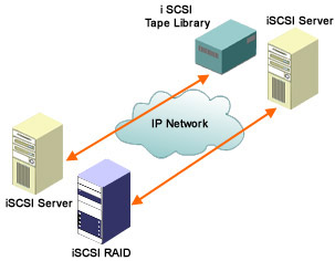
As shown in Figure 4-1-5, an iSCSI network comprises iSCSI initiators, such as file servers, and iSCSI targets, such as disk arrays and tape subsystems. The clients and storage devices support an Ethernet, Fast Ethernet, or the Gigabit Ethernet interface and the iSCSI protocol stack. This enables storage devices to be connected directly to switches or IP routers and appear as IP network entities.
For example, the network implemented in Figure 4-1-5 is a Gigabit Ethernet. Storage devices can be plugged directly into Gigabit Ethernet switches or IP routers.
Storage devices are connected to an iSCSI environment by using one of the following options:
-
iSCSI software driver
-
iSCSI software driver with TCP/IP offload engine (TOE) NIC
-
iSCSI sNIC with iSCSI offload engine or TOE
| Note | iSCSI offload engine is logic embedded on a network adapter. iSCSI offload engine processes the iSCSI protocol stack. The offload engine takes off the load of processing the iSCSI protocol stack from the operating system of an iSCSI target. TOE is similar to iSCSI offload engine. It is a logic embedded on a network adapter and processes the TCP protocol stack. When TOE is used, it takes off the load of processing the TCP protocol stack from the operating system. |
iSCSI Protocol Layers
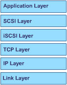
iSCSI is a combination of the SCSI protocol and the TCP/IP protocol. The iSCSI protocol is composed of six layers, as shown in Figure 4-1-6. Each layer performs a specific task to enable data transfer on an iSCSI network.
The Application layer is the topmost layer with which users directly interact. This layer represents the software application that is accessing a storage device.
The next layer is the SCSI layer, which encapsulates the requests issued by an end user into SCSI commands. The Application and SCSI layers represent the SCSI support, which is already present on servers and storage devices.
Next, is the iSCSI layer. The iSCSI layer encapsulates SCSI commands and data into network packets, which are known as iSCSI packets. This layer also encrypts the SCSI commands for security. This layer provides the mechanism for storage device mapping and data integrity check. It is this layer that connects a SAN with an IP network.
Below the iSCSI layer is the TCP layer that ensures network packets are transmitted. The TCP layer also provides congestion control service and a limited data integrity check.
The next layer is the IP layer. This layer allows data traffic to be routed between networks. The TCP and IP layers ensure reliable data transmission over potentially unreliable networks.
The layer next to the IP layer is the Link layer, which is the lowest layer. It represents a physical network, such as the Ethernet, the Gigabit Ethernet, or the Fibre Channel network. The TCP, IP, and Link layers represent the IP network infrastructure in an iSCSI setup.
| Note | The SCSI driver creates CDB from requests issued by the application and forwards them to the iSCSI layer. The driver also receives CDBs from the iSCSI layer and forwards the data to the application layer. The iSCSI layer encapsulates CDB into an iSCSI Protocol Data Unit (PDU) and forwards it to the TCP layer. The iSCSI layer also extracts the CDB from the PDU received from the TCP layer and forwards the CDB to the SCSI layer. |
How iSCSI Works
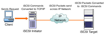
Figure 4-1-7 illustrates how data is transferred on a network, using the iSCSI protocol. On an iSCSI network, a client sends a request for data transfer to or from an iSCSI target. The operating system of the initiator processes the request and generates SCSI commands and data request. The SCSI commands and requests are then passed to the iSCSI software or hardware. In the iSCSI software or hardware, the commands and requests are encapsulated as a serial string of bytes that are preceded by iSCSI headers.
The encapsulated data is then passed to the TCP/IP layer that breaks the data into packets suitable for transfer over the IP network. The encapsulated data is also encrypted if the network over which the data is to be transferred is an insecure network.
At the receiving end, the storage controller recombines the packets and decrypts them into the original encapsulated SCSI commands and data. The storage controller then uses the iSCSI headers to send the SCSI commands and data request to the required drive. The drive executes the request issued by the client. If a request for data was sent, the data is retrieved from the drive, encapsulated, and returned to the client.
iSCSI Name and Address
Since iSCSI targets and initiators are participants on an IP network, iSCSI provides a name to each target and initiator to uniquely identify them on the IP network. The iSCSI names are 255-byte long. iSCSI also provides addresses to targets and initiators.
As shown in Figure 4-1-8, an iSCSI name is composed of three parts: type designator, naming authority, and unique identifier assigned by the naming authority. The naming authority can be operating system vendors, driver or NIC vendors, device vendors, gateway vendors, service providers, or customers.
Say, for example, an iSCSI name assigned to a device is fqn.com.ifs.array.host.115. In the example, the type designator is fqn and the naming authority is ifs.com. The unique identifier assigned by the naming authority is array.host.115.
The purpose of the iSCSI naming convention is to assist the discovery process and validate the identity of an initiator and a target during an iSCSI logon session between them.
In an iSCSI environment, the iSCSI name is used:
-
As an identifier for an initiator or target that may have more than one IP address and TCP port
-
As an identifier for the configuration that has multiple initiators or targets, or both, for a single IP address and TCP port
-
As a method to identify multiple paths to the same initiators or targets on different IP addresses and TCP ports
-
As an identifier for initiators and targets to enable them to identify each other, regardless of the IP address and TCP port mapping on intermediary firewalls
-
As a symbolic address for source and destination targets, for use in third-party commands
As shown in Figure 4-1-9, an iSCSI address is composed of an IP address, a TCP port, and an iSCSI name. The iSCSI address helps specify a single path to an iSCSI device. The iSCSI address is used during the discovery process. The iSCSI address is not used within normal connections between iSCSI initiators and targets. The iSCSI address is presented in a URL-like format as follows:
The separation of iSCSI names and iSCSI addresses ensures that a storage device has a unique identity on a network irrespective of its location on the network. The IP address and the TCP port number of a device changes if it is moved to a different network segment. As a result, the iSCSI address of the device changes. However, the iSCSI name of the device does not change. This allows the device to be rediscovered when it is moved to a different network segment.
Another benefit of iSCSI naming is that it is assigned by software and is independent of the supporting hardware. This allows a device driver on a host platform to be assigned a single iSCSI name, even if multiple storage NICs are used to attach the host to a network. Similarly, if a target device has multiple connections to a network for establishing redundant paths, the target device is identified as a single entity because of its iSCSI name.
iSCSI Session
An iSCSI initiator can send SCSI commands to a target only after it has established an iSCSI session. An iSCSI session is composed of one or more TCP connections. An iSCSI session between an initiator and a target is enabled through an iSCSI logon process. The logon phase should be completed for each TCP connection before it is used to transport SCSI commands.
The iSCSI logon process authenticates the initiator. It negotiates variable parameters between the iSCSI initiator and target. The initiator and target authenticate each other and set the security association protocol for the session during the iSCSI logon process.
The initiator begins the logon process by connecting to a popular TCP port. The target listens on the popular TCP port for incoming connections. If the iSCSI logon phase is successful, the target issues a logon accept status to the initiator. However, if the iSCSI logon phase is unsuccessful, the TCP connection is closed.
After an iSCSI session is established between the initiator and target, session IDs are generated to uniquely identify individual conversations between the initiator and target. A target responding to the logon request generates a unique target session ID (TSID). The TSID, in combination with the iSCSI name of the target, gives the session a unique identity within the network entity in which the target resides. Similarly, the iSCSI name and initiator session ID (ISID) of the initiator uniquely identifies the initiator within the network.
After the logon phase is completed, the iSCSI session enters the Full Feature phase for normal SCSI transactions. In the Full Feature phase, iSCSI PDUs are used to send CDB commands, status, and data.
iSCSI sessions and their associated connections normally remain open, waiting for additional SCSI commands from upper layer applications. However, you can selectively log off from previously established connections by using iSCSI logoff commands.
iSCSI Error Management
iSCSI errors may occur while transferring storage data over inherently unreliable network infrastructure, including the Internet.
One of the methods used to handle errors in the iSCSI environment is to ensure that both initiators and targets have the ability to buffer commands and responses until they are acknowledged. For example, when an initiator sends a SCSI write, the initiator stores the data that was just transmitted in its buffer, until it has received another Ready to Transmit (R2T) status from the target.
| Note | The R2T status indicates that previous data was received from the initiator and the target is now ready for more requests. |
During iSCSI sessions, two types of errors can occur, format error and digest or content error. A format error occurs when a PDU has missing or inconsistent fields within the frame. A Reject iSCSI PDU is sent to the initiator when a frame error occurs. The Reject PDU contains an offset indicator for the first bad byte detected in the PDU header.
Digest or content errors occur when data in either the data payload or header content is corrupted. Digest or content errors include Header Digest Error and Data Digest Error conditions. These errors also trigger a Reject PDU that, in turn, initiates recovery of the failed PDU. In case of a data digest error, a target can send a request for retransmission.

