IP Quality of Service (QoS) control mechanisms are the techniques used to implement QoS in a network. These mechanisms are based on various QoS principles, such as queuing, traffic policing, and traffic shaping. The QoS mechanisms include Call Admission Control (CAC), Resource Reservation Protocol (RSVP), and traffic engineering. Some forwarding mechanisms, such as load balancing and fragmentation, also help implement QoS.
This ReferencePoint describes QoS mechanisms and special cases of forwarding.
Call Admission Control
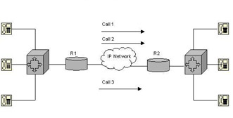
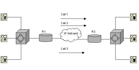
The CAC mechanism ensures that the voice traffic does not suffer latency, jitter, or packet loss, which can occur due to excess voice traffic on a network link. To ensure smooth transmission of voice traffic, CAC examines whether or not the network has sufficient resources to accept additional voice traffic. CAC protects one voice conversation from being interfered by other voice conversations. Figure 7-2-1 shows a network that can handle two voice connections simultaneously:
In Figure 7-2-1, voice data packets are queued for transmission. If the number of voice data packets exceeds the configured rate of transmission, the excess packets are dropped. The transmission link is configured to handle only two voice flows at a time. Introducing a third voice flow will result in the data packets being dropped. The queuing mechanism cannot identify the voice flow to which a data packet belongs. As a result, all the three voice flows experience packet loss and jitter.
CAC works on the principle of providing adequate QoS to fewer voice flows. Using CAC in the situation shown in Figure 7-2-1 will result in the third voice flow being tail dropped. This ensures the smooth transmission of the first two voice flows. In this way, CAC protects the data packets and, in turn, protects the quality of voice.
The device involved in voice flow transmission makes a decision about whether or not to allow transmission of a new voice flow. When the device makes this decision, it is said to have made a CAC decision. Depending on the devices making the CAC decision and the factors based on which this decision is made, Cisco defines the following categories of CAC tools:
-
Local CAC tools: When a new flow is introduced, the device that receives the new flow makes a CAC decision without consulting the other devices involved in the flow. The device also does not consider the network performance before making the decision.
-
Measurement-based CAC tools: When a new flow is introduced, the device that receives the flow checks the network performance by sending messages that measure delay and packet loss on the transmission link. Based on the network performance, the device makes a CAC decision.
-
Resource-based CAC tools: When a new flow is introduced, the device that receives the flow checks the resource used by itself and the other devices on the network. The new flow is admitted only if sufficient resources are available to handle it.
Table 7-2-1 lists various CAC tools:
| Tool | CAC Type | Description |
|---|---|---|
| Physical DSO Limitation | Local | CAC decision is based on whether or not a Digital Signal level zero (DSO) channel is available on the trunk. |
| Max-connections | Local | CAC decision is based on whether or not the number of connections currently present exceeds the configured number of maximum connections. |
| Voice-bandwidth for Frame Relay | Local | CAC decision is based on whether or not the rate at which data packets arrive at the router exceeds the configured Committed Information Rate (CIR) for the Voice over Frame Relay (VoFR). |
| Trunk conditioning | Local | CAC decision is based on whether or not the keepalive messages sent to the other end of the network are working. |
| Local Voice Busy-Out (LVBO) | Local | CAC decision is based on whether or not one or more interfaces have failed. If all the interfaces have failed, no connection exists and the trunk is placed in a busy-out state. |
| Advanced Busy-Out Monitor (AVBO) | Measurement-based | CAC decision is based on whether or not the network performance measurements are better than the configured impairment factor. If the measurements are not better than the impairment factor, the entire trunk is placed in the busy-out state. |
| PSTN Fallback | Measurement-based | CAC decision is based on whether or not the network performance measurements are better than the configured impairment factor. If the measurements are not better than the impairment factor, the incoming voice calls are permitted or rejected on a call-by-call basis. |
| Resource Availability Indicator (RAI) | Resource-based | CAC decision is based on whether or not the calculation of the available DSOs and Digital Signal Processors (DSPs) at the terminating gateway indicates adequate number of resources for the transmission of voice traffic. |
| GateKeeper Zone Bandwidth (GK Zone Bandwidth) | Resource-based | CAC decision is based on whether or not the gatekeeper believes that there is an oversubscription of the bandwidth into the required zones. |
| Resource Reservation Protocol (RSVP) | Resource-based | CAC decision is based on whether or not the RSVP reservation request flow can reserve the required bandwidth:
|
Resource Reservation Protocol
RSVP is a resource-based CAC tool that defines the messages used to request resource admission control and resource reservations. These messages conform to the integrated services (IntServ) model.
| Note | IntServ is a model defined in RFC 1633. |
The IntServ model supports best-effort traffic, real-time traffic, and controlled-link sharing. In an organizational network, some applications are critical to business while others are not. During congestion, QoS ensures that the data from critical applications is given priority and the other data is served only after the critical application data is served. Data in applications other than critical applications or priority applications is known as best-effort traffic. Real-time traffic refers to the data from applications that are considered to be mission critical. In controlled-link sharing, you can divide the traffic into categories and assign a minimum amount of bandwidth for each category during congestion. When there is no congestion in the network, various traffic categories share the available bandwidth.
In the IntServ model, applications use an explicit signaling message to inform the network about the nature of data they need to send. The signaling message also specifies the bandwidth and delay requirements of the applications. When the network receives the signaling message, it analyzes the nature of traffic specified and the available network resources. If the available network resources can handle the traffic efficiently, the network sends a confirmation message to the application. The network also commits to meet the requirements of the application as long as the traffic remains the same, as specified in the signaling message. After receiving the confirmation from the network, the application starts sending data.
RSVP defines the messages used to check the availability of resources when an application makes a QoS request. If the required resources are available, the network accepts the RSVP reservation message and reserves the resources for the requesting application. To provide the committed level of service to the requesting application, CISCO installs a traffic classifier in the packet-forwarding path. The traffic classifier helps the network identify and service the data packets arriving from the application for which the resources are reserved.
Most of the networks using RSVP and IntServ also use the DiffServ feature. For example, the tool used to provide minimum bandwidth commitments for DiffServ can also be used to dynamically reserve bandwidth for networks using IntServ and RSVP. CISCO has introduced a new feature called RSVP aggregation, which integrates resource-based admission control with DiffServ for enhanced scalability.
| Note | Across RSVP, data travels in a single direction, from source to destination. RSVP supports both unicast and multicast sessions. Support for multicast sessions allows merging multiple RSVP flows. The method of merging the flows varies according to the characteristics of the application using the flow. |
RSVP uses Weighted Fair Queuing (WFQ) to allocate buffers and schedule the data packets. WFQ is a packet scheduling technique that provides guaranteed bandwidth services and allows several sessions to share the same link. RSVP also uses specific WFQ queues to provide guaranteed bandwidth.
RSVP Levels of Service
To request for a level of QoS from the network, the applications must specify the acceptable levels of service. RSVP defines the following levels of service:
-
Guaranteed QoS: Used to guarantee that the required bandwidth will be provided to the traffic but with a fixed delay. Voice gateways that reserve bandwidth for voice traffic use this level of service.
-
Best-effort service: Used to ensure that the data from critical applications is given priority and the other data is served only after the critical application data is served.
-
Controlled-load network element service: Used to manipulate the behavior of the network that is visible to applications receiving best-effort service from the network elements when the network is not congested. This implies that if the application can work well when the network is not congested, the controlled load level RSVP service also works well. If the network works well with the controlled-load service, applications can assume low data loss, delay, and jitter. Data loss is low because queues are not filled up and data packets are not dropped when the network is not congested. If a packet loss occurs, it is due to transmission errors. Delay and jitter are low because queues are not filled up when the network is not congested and no queuing delay is introduced. Queuing delay is the main component for both transmission delay and jitter.
Distinct and Shared Reservations
RSVP supports the following types of reservations:
-
Distinct reservations: Refer to the bandwidth reservations for a flow that originates from only one source. In this type of reservation, a flow is created for each source in a session. Distinct reservations support single information streams that cannot be shared. Distinct reservation is most suited to a video streaming application, in which each source sends out a distinct data stream that requires admission and management. Each data stream requires a dedicated bandwidth reservation. RSVP refers to such distinct reservations as explicit, and installs the reservation using the Fixed Filter style of reservation.
-
Shared reservations: Refer to bandwidth reservations for a flow that originates from one or more sources. This type of reservation can be used by a set of sources or senders that do not interfere with each other. Shared reservations are applicable to a specific group and not to individual sources or destinations within a group. A shared reservation is most suited for audio or video conferencing applications. In audio or video conferencing, although there are multiple sources that send data, only a specified number of sources send data at the same time. As a result, each source does not require dedicated bandwidth reservation for data transmission. The same bandwidth reservation can be shared by all sources when they need to send data.
RSVP Soft State Implementation
RSVP is a soft state protocol. A soft state refers to the state where the router and the destination node can be updated using RSVP messages. During a reservation, RSVP maintains a soft state in the router and the host nodes. The RSVP soft state must be updated periodically using path and reservation request messages. If the soft state is not updated periodically, it is deleted. You can also use an explicit teardown message to delete the soft state. Deleting the soft state leads to the termination of reservation.
WFQ and RSVP
WFQ is a queuing mechanism that prioritizes data packets. WFQ transmits data packets with high IP precedence before transmitting data packets with low IP precedence. While prioritizing, WFQ uses the following formula to calculate the flow weight:
weight = 4096/(IP Precedence + 1)
When the data packets arrive at the queues, WFQ sorts out the data packets and assigns a sequence number to each data packet. WFQ then transmits the data packet that has the lowest sequence number. The sequence number of a data packet is calculated using the following formula:
sequenceNumber = currentSequenceNumber + (weight * length)
In this formula, the value of currentSequenceNumber depends on the conditions described in Table 7-2-2:
| Condition | Value |
|---|---|
| Queue is empty | Equal to the sequence number of the last data packet that was queued for transmission in the subqueue |
| Data packet is the first packet in the subqueue | 0 |
| Subqueue is not empty | Equal to the sequence number of the last packet in the subqueue |
After assigning the data packets to a flow, the individual flows are monitored and the volume of data flow is constantly observed. The flows are then assigned to high-volume or low-volume queues. Low-volume queues carry data packets from interactive applications and as a result, have a high priority over the high-volume queues that carry bulk data packets.
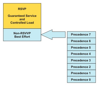
WFQ does not guarantee minimum bandwidth. Instead, WFQ evaluates the length of the data packets and the precedence of the data packets in all the queues and tries to provide access to all the queues. At any point in time, you can allocate only 75 percent of the bandwidth of an interface to RSVP. The remaining 25 percent of the bandwidth is available for best-effort traffic, as shown in Figure 7-2-2:
After allocating the bandwidth, WFQ re-assesses the queues based on the sequence number and transmits the data packets with the smallest sequence number.
WFQ is the default queuing mode used in interfaces that run at or below E1 speed, which is 2.048 Mbps or less.
In some cases, although WFQ is the default queuing mechanism, you may need to code WFQ explicitly to change the default options of the links. To change the default options of the links, use the following command:
fair-queue
[congestive-discard-threshold
[dynamic queues]
[reservable queues]]]
In this command:
-
congestive-discard-threshold is the maximum number of data packets that a queue can hold. The default value for this parameter is 64.
-
dynamic queues is the number of subqueues. The default value for this parameter is 256.
-
reservable queues is the number of reservable queues used for RSVP flows.
Low Latency Queuing and RSVP
CISCO supports the service levels provided and defined by RSVP when it is used in conjunction with other QoS queuing mechanisms. For example, RSVP has its own set of reserved queues within Class-Based Weighted Fair Queuing (CBWFQ) for traffic with RSVP reservations. These reserved queues enable RSVP to create hidden queues that receive low weights. In CBWFQ, queues with lower weights receive service on priority.
Although the reserved hidden RSVP queues feature works well with non-voice data, it does not work well with voice data. This is because although the RSVP queue receives low weights, the data packets in the RSVP queues are not assured priority over the other data packets. As a result, to configure RSVP for voice data, the voice data packets must first be classified into the priority queue. Configuring RSVP to place voice-like data packets into the priority queue (PQ) of Low Latency Queuing (LLQ) solves this problem of priority.
| Note | LLQ is a queuing mechanism that ensures quality of voice conversations. It prioritizes the voice data packets over the other data packets at the router egress or the output interface of the router. |
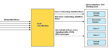
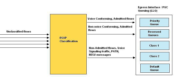
RSVP uses a profile to classify a data packet as a voice data packet. The profile specifies the packet sizes, arrival rates, and other parameters to determine whether or not a data packet can be classified as a voice data packet. RSVP makes reservations and puts all the voice-like data packets into the LLQ PQ and the other data packets into the RSVP queues, as shown in Figure 7-2-3:
When RSVP and LLQ work in conjunction, RSVP first checks the data packet that arrives at egress. If RSVP identifies that data packet as a voice data packet, it puts the data packet in the PQ of LLQ. If the data packet is not a voice-like data packet but has some RSVP reservations, RSVP puts the data packet in the normal RSVP queue. If the data packet is not a voice-like data packet and does not have any RSVP reservations, LLQ classifies the data packet, as it would normally do.
RSVP and LLQ do not share the same bandwidth and this leads to inefficient use of bandwidth. All the classes or categories of data packets are allocated bandwidth during the configuration of the egress interface. Bandwidth is not allocated to RSVP because RSVP requests for bandwidth only when the traffic flow begins. After bandwidth is allocated to other queues, the remaining bandwidth is allocated to RSVP. The low bandwidth allocated to RSVP can reduce the quality of voice data.
RSVP for VoIP
Reservations are initiated from one host to another. In RSVP for VoIP, the VoIP router initiates the reservation.
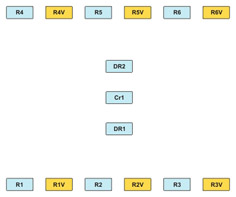
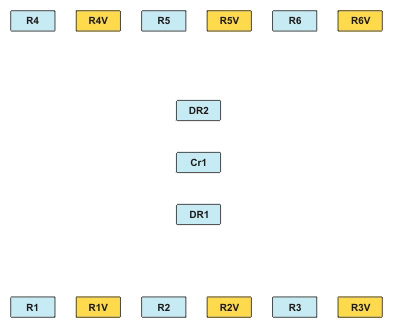
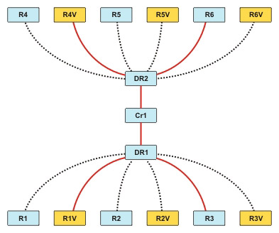
For example, an organization has six branch offices. Each branch office has two routers, one for VoIP, and the other for non-voice traffic, as shown in Figure 7-2-4:
R1, R2, R3, R4, R5, and R6 represent the routers that are reserved for non-voice data. R1V, R2V, R3V, R4V, R5V, and R6V represent the routers that are reserved for VoIP data. DR1 and DR2 represent the distribution routers and Cr1 represents the core router.
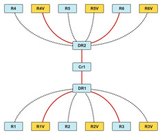
In Figure 7-2-4, only the VoIP router needs reserved bandwidth. The branch office routers connect to one of the two distribution routers. The distribution routers, in turn, connect to a core router, as shown in Figure 7-2-5:
R1V is connected to R4V, while R3 is connected to R6 though the distribution routers, DR1 and DR2 and the core router, Cr1.
In Figure 7-2-5, you must reserve end-to-end bandwidth among the VoIP routers at each branch.
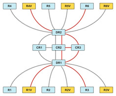
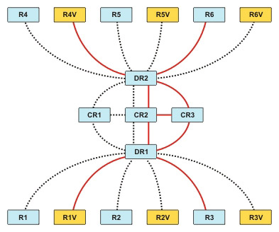
If you implement fault tolerance, all the interfaces in possible paths must be RSVP-enabled, else the path cannot be used for RSVP, as shown in Figure 7-2-6:
Fault tolerance is implemented by introducing additional core routers, CR2 and CR3, and defining the routing path for the routers in case the primary core router fails.
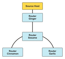
If the RSVP traffic is uni-cast, each flow will be separate and will consume separate resources in a shared medium, as shown in Figure 7-2-7:
When the RSVP traffic is multicast, the flows can merge in a common medium and save bandwidth.
RSVP Reservations
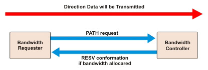
The direction of the RSVP setup is exactly opposite to the direction in which bandwidth is reserved. The process of making a RSVP reservation is shown in Figure 7-2-8:
The RSVP reservation process involves the following steps:
-
The sender transmits a reservation request using the RSVP PATH message to the receiver. A reservation can be made in the following ways:
-
Fixed filter: Used when there is a single address.
-
Wild card filter: Used when there exists a defined list of addresses at the source or demand side.
-
Shared explicit: Used to identify the resources that can be used at the supply side.
-
-
The routers that are in the reservation path and are authorized to allocate bandwidth forward the PATH message to the next router.
-
When the PATH message reaches the last router in the path, that router sends an RESV message back to the sender along the same path. This confirms the reservation.
| Note | If the end-to-end path changes midway through this process, the bandwidth reservation needs to be done once again. |
An RSVP-enabled interface releases a reservation if it does not receive a PATH message. This leads to the unavailability of bandwidth when required. To avoid this situation, the Internetworking Operating System (IOS) provides commands that enable you to do one of the following:
-
Force a router to believe it is continually sending a PATH message (ip rsvp sender).
-
Force a router to send continuous PATH messages even when there is no RSVP request to do so.
RSVP Synchronization Configuration
You can configure RSVP for use with H.323 by enabling RSVP and adding a few commands to the H.323 dial peers. By default, RSVP is disabled on each interface so that it is backward compatible with systems that do not implement RSVP. To enable RSVP for IP on an interface, use the following command:
ip rsvp bandwidth
This command starts RSVP and sets the maximum bandwidth for single and multiple RSVP flows. The default maximum bandwidth is up to 75 percent of the total available bandwidth on the interface.
To configure a network to use RSVP, regardless of whether or not it is used for voice calls, use the following command on every link on the network:
ip rsvp bandwidth
describes the options available for the acc-qos and req-qos commands:
| Options | Description |
|---|---|
| best-effort | Specifies that RSVP makes no bandwidth reservations. |
| controlled-load | Specifies that RSVP guarantees a single level of preferential service. The controlled-load admission ensures that preferential service is provided even during network overload or congestion. |
| guaranteed-delay | Specifies that RSVP reserves bandwidth and guarantees a minimum bit rate and preferential queuing if the reserved bandwidth is not exceeded. |
Basic RSVP Configuration
RSVP is disabled by default. You must enable RSVP on the required interface and must allocate a maximum reservable bandwidth to RSVP. Some of the important configuration commands are:
-
Configuring RSVP on an interface: You can enable RSVP on an interface using the following command:
ip rsvp bandwidth [interface-kbps] [single-flow-kbps]
The default maximum bandwidth is 75 percent of the total interface bandwidth but you can set a different value. You can also set the maximum bandwidth allowable for a single flow.
When you configure RSVP on a subinterface, you can reserve either the subinterface bandwidth or the default bandwidth on the physical interface, whichever is less.
-
Configuring a router to receive PATH message: You can configure the router to periodically receive an RSVP PATH message from a sender or previous hop routes, using the following command:
ip rsvp sender
session-ip-address
sender-ip-address [tcp | udp | ip-protocol]
session-dport
sender-sport
previous-hop-ip-address
previous-hop-interface -
Configuring a router to receive reservation messages: You can configure the router to continuously receive an RSVP RESV message from a sender, using the following command:
ip rsvp reservation
session-ip-address
sender-ip-address [tcp | udp | ip-protocol]
session-dport
sender-sport
{ff | se | wf} {rate | load}
bandwidth burst-size -
Configuring RSVP to restrict the number of neighbors that request reservations: It is a best practice to limit the number of neighbors that can request reservations on the network. Failing to do this will result in loss of control of bandwidth requirements in your network. You can specify the number of routers that can offer reservations by using the following command:
ip rsvp neighbors access-list-number
Table 7-2-4 lists the parameters used in RSVP commands and their description:
| Parameter | Description |
|---|---|
| session-ip-address | Refers to the IP address of the sending host |
| {tcp | udp | ip protocol} | Refers to the specific TCP, UDP, or IP protocol number |
| previous-hop-ip-address | Refers to the address or name of the receiver or the router closest to the receiver |
| previous-hop-interface | Refers to the previous hop interface or subinterface, which can be Ethernet, loopback, serial, or null |
| next-hop-ip-address | Refers to the address or name of the receiver or the router closest to the receiver |
| next-hop-interface | Refers to the next hop interface, which can be Ethernet, loopback, serial, or null |
| session-dport session-sport {ff | se | wf} | Refers to the source and destination port numbers |
| {ff | se | wf } | Refers to the RSVP reservation style
|
| {rate | load} | Refers to QoS
|
| bandwidth | Refers to the bandwidth to be reserved in Kbps (up to 75 percent of the interface) |
| burst-size | Refers to the size of the burst in kilobytes |
RSVP Configuration
To originate or terminate voice traffic using RSVP, you need to perform the following steps on the gateway:
-
Turn on the synchronization feature between RSVP and H.323. This synchronization is turned on by default when Cisco IOS Release 12.1(5)T or later is loaded.
-
Configure RSVP on the originating and terminating ends of the VoIP dial peers by:
-
Configuring both the request QoS (req-qos) and the accept QoS (acc-qos) commands.
-
Selecting the guaranteed-delay option for RSVP to function as a CAC tool.
-
-
Enable RSVP and specify the maximum bandwidth on the interfaces that the call will traverse.
Table 7-2-5 lists the commands to configure RSVP:
| Command | Description |
|---|---|
| ip rsvp bandwidth total-bandwidth per-reservation-bandwidth | Defines the cumulative total and per-reservation bandwidth limits. This is an interface configuration command. |
| call rsvp-sync | Enables H.323 RSVP synchronization. This is a global configuration command. |
| ip rsvp pq-profile | Specifies the criteria to determine, which data packets are placed in the priority queue. This is a global configuration command. |
| req-qos {best-effort | controlled-load | guaranteed delay} | Specifies the required QoS requested for the data packets to reach a specified VoIP dial peer. This is a dial peer configuration command. |
| acc-qos {best-effort | controlled-load | guaranteed delay} | Specifies the acceptable QoS for any inbound and outbound data call on a VoIP dial peer. This is a dial peer configuration command. |
| fair queue [congestive-discard-threshold [dynamic-queues [reservable-queues]]] | Enables WFQ on an interface with the last parameter defining the number of queues created by RSVP. This is an interface configuration command. |
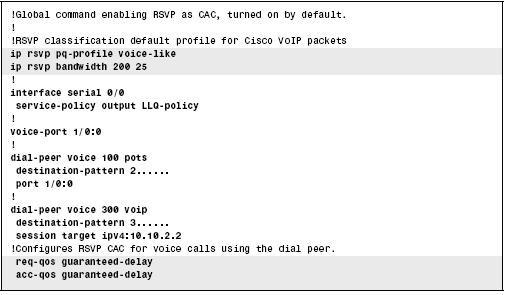
Figure 7-2-9 shows the commands you can use to configure RSVP with LLQ:
In Figure 7-2-9:
-
The call rsvp-sync command enables synchronizing H.323 and RSVP. This synchronization allows new call requests to reserve bandwidth using RSVP.
-
The ip rsvp pq-profile command instructs IOS to classify voice packets into a LLQ PQ, assuming LLQ is configured on the same interface as RSVP.
-
The service-policy command enables a policy map that defines LLQ on interface serial 0/0.
-
The ip rsvp bandwidth command reserves a total of 200 kbps bandwidth, with a per-reservation limit of 25 kbps.
-
The req-qos and acc-qos commands instruct IOS to make RSVP reservation requests when new call requests are made.
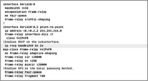
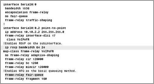
You can also configure RSVP with Frame Relay Traffic Shaping (FRTS). Figure 7-2-10 shows the various commands to configure RSVP with FRTS:
Monitoring and Troubleshooting RSVP
The first step in troubleshooting RSVP is to verify synchronization. If synchronization is not verified, RSVP cannot prevent the H.323 gateway from consuming more resources than available and moving into an alerting state. To verify synchronization, use the following command:
show call rsvp-sync conf
Figure 7-2-11 shows the output of the show call rsvp-sync conf command:
The other commands to monitor and troubleshoot RSVP are described in Table 7-2-6:
| Command | Mode and Function |
|---|---|
| show ip rsvp neighbor [interface-type interface-number] | Displays current RSVP neighbors. |
| show ip rsvp request [interface-type interface-number] | Displays RSVP-related request information being requested upstream. |
| show ip rsvp reservation [interface-type interface-number] | Displays RSVP-related receiver information currently in the database. |
| show ip rsvp sbm [detail] [interface-name] | Displays information about a Subnet Bandwidth Manager (SBM) configured for a specific RSVP-enabled interface or for all RSVP-enabled interfaces on the router currently in the database. |
| Show ip rsvp sender [interface-type interface-number] | Displays sender information related to RSVP PATH available in the database. |
You can use the show call rsvpsync stats command to view the statistics of all the calls that have attempted RSVP reservations. Figure 7-2-12 shows a sample output of the show call rsvpsync stats command:
If the output of the show call rsvpsync stats command shows a high number of errors or reservation timeouts, there may be a network or configuration issue.
shows a sample output of the show ip rsvp installed command:
In Figure 7-2-13, the reserved bandwidth for Ethernet 2/1 interface can be calculated by adding the bandwidth provided for each connection, as shown in the following calculation:
4444 kbps + 44 kbps + 98 kbps + 1 kbps = 187 kbps
You can compare the calculated bandwidth with the maximum bandwidth configured for the interface. The maximum bandwidth configured for the interface can be obtained using the ip rsvp bandwidth command. If the reserved bandwidth is approaching the maximum configured bandwidth, RSVP rejections can occur.
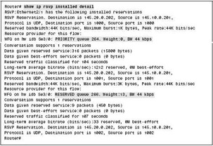
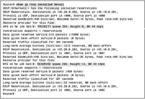
To view detailed information about the reservations on the local interfaces, you can use the show ip rsvp installed detail command. Figure 7-2-14 shows a sample output of the show ip rsvp installed detail command:
Traffic Engineering
Traffic engineering is the ability of the router to move network traffic from one route to another. This change in route helps route the traffic around the known points of congestion on the network and make effective use of the available bandwidth.
One of the important principles of avoiding network congestion is to control the transmission of overhead traffic, such as nonessential routing updates. The first step towards implementing traffic engineering is to use static routes that transmit the traffic through a path that is manually engineered for better bandwidth. Most networks use destination-based static routing.
You can also use policy routing to implement traffic engineering. Policy routing is an extension of static routing. Policy routing routes network traffic based on IP precedence, flow, or TCP/UDP port type.
Policy-Based Routing
Policy-based routing (PBR) enables you to route a packet based on information other than the destination IP address. In some situations, you may require a few data packets to take a different path. For example, one path through the network may be more secure than the other available paths and so you direct some data packets through a longer but more secure path. The data packets that can tolerate high latency can be routed through a path that uses satellite links.
PBR supports packet marking and policy routing. PBR uses the packet-marking feature to select a different route for QoS reasons. For example, PBR selects a different route to affect the latency of a packet. You can also use PBR just for classification and marking, without choosing a different route. PBR only processes packets entering an interface, you cannot enable it for packets exiting an interface. PBR needs to process packets before a routing decision is made.
Another difference between PBR and the other classification and marking tools, such as CB marking and CAR, is that PBR can classify data packets based on routing information, instead of depending on the information in the frame or packet header. PBR can look up the routing table for an entry that matches the destination address of a data packet and then classify the data packets based on the route information. For example, the data packet can be classified based on the metric associated with that route, the source of the routing information, or the next hop interface associated with the route. This routing information does not help differentiate between different types of traffic. For example, an FTP server, an IP Phone, a video server, and a Web server may all be in the same subnet but the routing information about that subnet cannot help PBR differentiate between the different types of data packets.
Table 7-2-7 lists the PBR configuration commands:
| Command | Description |
|---|---|
| ip local policy route-map map-tag | Specifies that policy routing must be applied on the packets that originate from the specified router. This is a global command. |
| ip policy route-map map-tag | Specifies a route map that classifies the data packets. It also specifies actions such as selecting a different route or setting IP precedence. This is an interface subcommand. |
| route-map map-tag [permit |deny] [sequence number] | Creates a route map entry. This is a global command. |
| match ip address [access-list-number | access-list-name] [...access-list-number | ....access-list-name] | Matches the IP packets based on the parameters matched with the specified access list. This is a route-map subcommand. |
| match length minimum-length maximum-length | Matches the IP packets based on the specified length. This is a route-map subcommand. |
| set ip precedence number | name | Sets the IP precedence value using the decimal number of name. This is a route-map subcommand. |
| set ip next-hop ip-address [...ip address] | Specifies the IP addresses of the next-hop routers that must be used to forward the data packets matching this route-map entry. This is a route-map subcommand. |
| ip route-cache policy | Enables fast-switching of data packets routed by PBR. This is a global command. |
Table 7-2-8 lists the various PBR exec commands:
| Command | Description |
|---|---|
| show ip policy | Lists configured PBR details and statistics for number of packets matched by each clause. |
| show route-map | Lists statistical information about packets that match with the route map. PBR uses route maps to classify and mark traffic. |
Verifying the Next Hop
If CISCO Discovery Protocol (CDP) is enabled on an interface, policy routing proceeds only if the next hop is reachable. The next hop may be reachable after a certain time interval. This process increases the delay and reduces network performance but improves the reliability of the network because it ensures that the data packet is not lost if the next hop is not reachable. The following command forces the router to verify that the next hop is reachable:
set ip next-hop verify-availability
The next hop device may or may not be CDP-enabled. If the next hop is not CDP-enabled, the local router tries to find an alternative next hop in the route map. If the local router does not find an alternative next hop, the data packet is routed to destination-based routing.
Controlling Routing Updates at Interfaces
Advertising routes or accepting the advertised routes can reduce network performance and security. As a result, it is not advisable to advertise the routes from a particular interface or accept the routes that originate from a particular interface. To suppress advertising routes from an interface, use the following command:
passive-interface type number
In this command, type number specifies the interface that will be set as passive to suppress advertising the routes.
Whether or not declaring the interface as passive will affect its advertising on other interfaces depends on the protocol being used. Whether or not the interface will listen to other routing announcements also depends on the protocol being used.
To ensure enhanced network performance in an enterprise-wide network, you need to ensure that not all routing updates are transmitted to all the routers on the network. Instead, you must configure the routing updates in a way that all routers send their routing updates to the distribution routers but only receive the default routing updates from the distribution routers. This process helps prevent network congestion due to transmission of routing updates. You can use the following command to suppress advertising of individual routes or group of routes:
distribute-list
{access-list-number | access-list-name} out
[interface-name | routing-process | autonomous-system-number]
Special Cases in Forwarding
Data can be transmitted or forwarded as single data packets or a stream of data packets. When single data packets are forwarded over the network, the network performance is affected. When streams of data packets are forwarded over the network, the load on the router processors and the bandwidth are affected. The role of Routing Information Bases (RIBs), Forwarding Information Bases (FIBs), and caches in forwarding are as follows.
-
RIB is the main routing table. You can identify and manage RIB by using the path determination process.
Note Path determination uses a Reduced Instruction Set Computer (RISC) or Complex Instruction Set Computer (CISC) processor chip.
-
Forwarding Information Base (FIB) is a subset of RIB. FIB is used during the packet forwarding process.
Note Packet forwarding uses an Application-Specific Integrated Circuit (ASIC).
-
Generally, when a cache miss occurs, the entire cache of the routing table is invalidated and rebuilt. During this time, the network traffic is placed on process-switch mode.
While router updates are being processed, there is a pause or break in forwarding data packets on the network. In Cisco, the forwarding modes are referred to as switching modes. The switching modes that are available include process switching, fast switching, Cisco Express Forwarding (CEF), Distributed CEF (dCEF), and Netflow switching. Based on the interfaces used, you can set these switching modes.
Each switching mode uses a different lookup table, as described in Table 7-2-9:
| Mode | Lookup Table |
|---|---|
| Process switching | Routing Information Base (RIB) |
| Fast switching | RAM cache |
| Cisco Express Forwarding | Forwarding Information Base (FIB) |
| Distributed Cisco Express Forwarding | Multiple FIB |
| NetFlow switching | Flow table |
Delays in forwarding data packets across the network can be due to various factors, such as connection speed of the interface to the server, processing capacity of the server, and network bandwidth. Delays can also be due to increased lookup time, medium of transmission, and switches themselves.
The various mechanisms used for forwarding data packets are load balancing and fragmentation.
Load Balancing
Load balancing is one of the methods for congestion management. In most cases, load balancing is not considered the best solution to manage congestion on the network because it can lead to the following problems:
-
Heavy processor utilization
-
Heavy load on the destination hosts due to a large number of out-of-sequence data packets
-
Inefficient use of bandwidth
Load balancing can also be referred to as load sharing. You can use load balancing in various situations. For example, when you have multiple parallel links to an ISP, appropriate load sharing can optimize the bandwidth on the links. Some of the load-balancing mechanisms include round robin, per destination, and source-destination hash.
Round Robin
The round robin method is also referred to as per-packet method. In the round robin method, one server IP address is handed out and it moves to the end of the list, the next server IP address is handed out and it moves to the end of the list. This process is repeated for all the servers being used. When you use this method, there is a heavy load on the CPU. This method uses the process-switching mode and is best suited to maintain bandwidth and convergence to the link but not to maintain the data packets in sequence.
For example, you may need to balance the load over a network connection having two routers with two parallel links. The round robin method utilizes the bandwidth to the optimum level but does not maintain the sequence of data packets. This increases the load on the destination hosts and decreases the performance of the router because of the increase in the processing time. The round robin method speeds up the process of convergence of links after connection failures.
Reasons for Increased Processor Load
When data packets are forwarded on the network, the forwarding process must identify the interface that can be used to forward the next data packet and the number of interfaces that exist within that particular load-sharing group. This information is available only in the main RIB and has to be retrieved using the process switching mode. In this mode, the load on the processor is very high.
Reasons for Resequencing of Packets
The round robin method reorders or resequences the data packets in the queue. This resequencing occurs mainly because different links on the network have different delays. The round robin method implements load balancing per-packet over N queues. The first data packet is forwarded over the first queue, the second packet over the second queue, and so on. The nth packet is forwarded over the Nth queue and the (n+1)th data packet is forwarded over the first queue. If any one of the queues has a delay, the data packets sent through the later queues are transmitted earlier and reach the destination before the data packet from the delayed queue. This is known as out-of-order delivery. When there are more links and several source-destination pairs, it is certain that there would be more delays. In such cases, out-of-order delivery or reordering of data packets occurs.
Per Destination
The per-destination method uses the fast switching mode. The load on the CPU is less when this method is used. This method is beneficial in the case of multiple destinations. The CPU may have unbalanced loads when there are fewer destinations on the network. When using this method, there is no considerable improvement in convergence on the network but data packets remain in sequence.
Per-destination load balancing, which uses the fast switching mode, has a destination-level granularity. This method is best suited in situations where there are multiple destinations and multiple paths. If this method load balancing is not used in these situations, most of the network traffic is redirected towards a single path. This leads to network congestion, also known as pinhole congestion.
Source-Destination Hash
The source-destination hash method uses both the CEF and dCEF switching modes. When CEF is used, the load on the CPU is neither too high nor too low and when dCEF is used, the load on the CPU is low. This method is suitable when you need to spread the load over multiple next-hop links. When using this method, there is no considerable improvement in convergence on the network but the data packets remain in sequence.
Source-destination hash is implemented in CEF and has a flow-level granularity. The flow-level property of this method helps avoid reordering of data packets or out-of-sequence delivery of data packets. The source-destination hash distributes the flows randomly over the existing number of links.
The network traffic is also regularized and the load is equalized because of increased number of flows. The possibility of pinhole-congestion still exists. You can reduce this by appropriately including the source TCP/UDP port number, the destination TCP/UDP port, or both in the hash, in addition to the source and destination IP addresses.
The limitations of this method are, as follows:
-
The size of the flow tables increases. As a result, more emphasis needs to be on TCP/UDP port number distribution.
-
Although the load between nearby routers is adjusted, the network congestion may happen on routers that are several hops away.
Fragmentation
Fragmentation refers to breaking the data packets into fragments for easy transmission on the network. Fragmentation is used only in conditions when no transmissions would take place without it. Else, it is used as a last resort to forward data packets.
Fragmentation leads to several performance problems, such as:
-
Over utilization of CPU
-
Requirement of extra buffers
-
Inefficient forwarding path
-
Arrival of out-of-sequence data packets
-
Increased load on processors at the destination
-
Failure of transfer of data packets at the destination
The use of voice data packets has introduced various forms of fragmentation that reduce the delay in forwarding data packets. You can use fragmentation with different protocols for various reasons. For example, it is optional to use fragmentation with the IP protocol. In this case, you can use fragmentation to increase the interoperability between various applications. In the case of frame relay, you can use fragmentation to minimize the latency queuing for Voice over Frame Relay (VoFR).
Forwarding Delay from Router Ingress to Egress
When data packets are transmitted internally, the forwarding delay is almost negligible and does not have any major impact on the network performance. On the other hand, serialization delays have a greater impact on the network performance.
When data packets from multiple hosts are transmitted over the network to multiple destinations, the forwarding delay is high. This high delay results in an increase in the forwarding overhead and load on the processors. The forwarding overhead and processor load have a considerable impact on the network performance.
Several software-based and hardware-based mechanisms have been implemented on networks to reduce the forwarding overheads and improve network performance. Some examples include fast-switching and hardware-assisted switching, such as silicon switching.
The Ping and Traceroute Commands
While forwarding data packets on the network, you must take into account the performance of the network. You can use the traceroute and ping commands to get information about the performance of the network, network path of the data packet, and network congestion.
The Ping Command
The ping command is used to troubleshoot the accessibility of applications on the network. This command uses a series of Internet Control Message Protocol (ICMP) Echo messages to determine:
-
The state of a remote host, active or inactive
-
The round-trip delay in communicating with the host
-
Packet loss
The ping command sends an echo-request data packet to an address and waits for a reply from the destination. The ping is successful only if the echo-request data packet reaches the destination and the destination is able to send an echo-reply data packet back to the source within the timeout period.
| Note | The default value of the timeout is two seconds on Cisco routers. |
The Traceroute Command
The traceroute command is used to identify the actual routes taken by the data packets to their destination. The router sends out a sequence of User Datagram Protocol (UDP) datagrams encapsulated in IP packets to an invalid port address at the remote host.
On the first traceroute pass, three datagrams are sent, each with a Time-To-Live (TTL) field value set to 1, which causes the datagram to timeout as soon as it hits the first router in the path. This router then responds with an ICMP TTL Exceeded message indicating that the datagram has expired.
| Note | Different implementations of the traceroute command send the test message in different ways. |
On the second traceroute pass, three other UDP messages are sent, each with the TTL value set to 2. This TTL value of 2 again causes the second router to return ICMP TTL Exceeded messages. This process repeats until the data packets actually reach the destination or a hop count limit is reached. By sending these UDP messages, you can record the source of each ICMP Time Exceeded Message. This recorded information provides a trace of the path of the data packet to its destination.
Effect of Firewalls and Filters
Filters and firewalls implemented on the network can affect the traceroute and ping commands in different ways.
There is no specific UDP port number associated with UDP. However, the UDP port number is generally in the range of 33,000, which is high. Traceroute could fail because a traffic policy implemented on the network may not permit unexpected traffic to high-numbered UDP ports.
Ping can fail if either the inbound or outbound ICMP is blocked.
Traceroute can fail if the returning ICMP TTL Exceeded message is blocked on the network.
Because of filters and firewalls installed on the network, you can sometimes successfully ping the destination but you may not be able to trace the path of the data packet to the destination. In other situations, you may be able to trace the path but the ping command may fail.
Traceroute and Ping Command Results
Although the results of the traceroute and ping commands give valuable information about the traffic and performance of the network, in many cases, you cannot take decisions solely based on these results. This is because the ping and traceroute commands provide useful information only in ideal environments where there is no other traffic. In a real-world production environment, ping and traceroute information may not be accurate. When the destination router processes the information, there are chances that the information may be skewed.

