 Requiring Address Translation
![]() In version 6 of the OS and earlier, you always had to configure a translation rule for a packet; otherwise, if the packet couldn’t be matched against existing translation rules, it was dropped. This rule applied whether the traffic was inbound or outbound.
In version 6 of the OS and earlier, you always had to configure a translation rule for a packet; otherwise, if the packet couldn’t be matched against existing translation rules, it was dropped. This rule applied whether the traffic was inbound or outbound.
![]() Starting in version 7, translation is optional and not required. To require address translation, use the following command:
Starting in version 7, translation is optional and not required. To require address translation, use the following command:
asa(config)# nat-control
![]() Once you require address translation with the nat-control command, the same rules apply as they did in version 6: if there is no matching translation policy for inbound or outbound traffic, and address translation is enabled, the packet is dropped. There is one exception to this policy: if the two interfaces involved in the communication have the same security level, then you don’t need an address translation rule to move packets between them.
Once you require address translation with the nat-control command, the same rules apply as they did in version 6: if there is no matching translation policy for inbound or outbound traffic, and address translation is enabled, the packet is dropped. There is one exception to this policy: if the two interfaces involved in the communication have the same security level, then you don’t need an address translation rule to move packets between them.
| Note | |
 Configuring Dynamic Address Translation
![]() Configuring dynamic address translation (NAT or PAT) involves a two-step process:
Configuring dynamic address translation (NAT or PAT) involves a two-step process:
-
 Identifying the local addresses that will be translated
 -
 Creating global address pools that local addresses can be translated to
![]() The order in which you configure these two items doesn’t matter. The following sections will discuss how to set up dynamic NAT and PAT translation rules, as well as cover many different examples of dynamic translation examples.
The order in which you configure these two items doesn’t matter. The following sections will discuss how to set up dynamic NAT and PAT translation rules, as well as cover many different examples of dynamic translation examples.
Identifying Local Addresses for Translation
![]() To identify the local addresses that can be translated, use the nat command:
To identify the local addresses that can be translated, use the nat command:
ciscoasa(config)# nat (logical_if_name) NAT_ID
                      local_IP_addr subnet_mask
                      [tcp] max_TCP_conns [embryonic_conn_limit]
                      [udp max_UDP_conns] [dns] [norandomseq]
![]() The nat command specifies which local addresses will be translated to the pool specified in the global command. The logical name of the interface where the local devices are located appears in parentheses (“( )”), like (inside), for example.
The nat command specifies which local addresses will be translated to the pool specified in the global command. The logical name of the interface where the local devices are located appears in parentheses (“( )”), like (inside), for example.
![]() The NAT_ID ties the nat and global commands together, creating a policy. With one exception, the number you use for the NAT_ID (the policy number) doesn’t matter. There is a special instance of using a NAT_ID number: if you enter 0, you are telling the appliance that the addresses that follow this in the nat command should not be translated. Cisco refers to this feature as Identity NAT, which was introduced in version 6.2. You might want to use Identity NAT if you have a mixture of public and private addresses being used on the inside of your network—for the machines with public addresses, you can disable NAT by using the nat 0 command and specifying the address or addresses of those devices.
The NAT_ID ties the nat and global commands together, creating a policy. With one exception, the number you use for the NAT_ID (the policy number) doesn’t matter. There is a special instance of using a NAT_ID number: if you enter 0, you are telling the appliance that the addresses that follow this in the nat command should not be translated. Cisco refers to this feature as Identity NAT, which was introduced in version 6.2. You might want to use Identity NAT if you have a mixture of public and private addresses being used on the inside of your network—for the machines with public addresses, you can disable NAT by using the nat 0 command and specifying the address or addresses of those devices.
![]() If you specify a network number for the local_IP_addr, also specify the appropriate subnet mask. By entering a network number and a subnet mask, you are specifying a range of addresses to be translated. To translate all addresses on the inside interface, use the following syntax:
If you specify a network number for the local_IP_addr, also specify the appropriate subnet mask. By entering a network number and a subnet mask, you are specifying a range of addresses to be translated. To translate all addresses on the inside interface, use the following syntax:
ciscoasa(config)# nat (inside) 1 0.0.0.0 0.0.0.0
![]() Then tie the pool/NAT ID “1” to the corresponding global command. Note that you can abbreviate 0.0.0.0 0.0.0.0 to just 0 0.
Then tie the pool/NAT ID “1” to the corresponding global command. Note that you can abbreviate 0.0.0.0 0.0.0.0 to just 0 0.
![]() You can also limit the total number of TCP connections (max_TCP_conns) as well as the number of half-open/embryonic TCP connections (embryonic_conn_limit). Starting in version 7.0, you can also limit the maximum number of UDP connections. If you don’t configure connection limits for devices that match a translation policy, then whatever the conn table supports is what the appliance will allow. I’ll discuss the use of these parameters in more depth later in the “TCP SYN Flood Attacks” section.
You can also limit the total number of TCP connections (max_TCP_conns) as well as the number of half-open/embryonic TCP connections (embryonic_conn_limit). Starting in version 7.0, you can also limit the maximum number of UDP connections. If you don’t configure connection limits for devices that match a translation policy, then whatever the conn table supports is what the appliance will allow. I’ll discuss the use of these parameters in more depth later in the “TCP SYN Flood Attacks” section.
![]() It is highly recommended that you do not turn off the TCP Sequence Number Randomization feature of the appliance. You should only do this if this feature is causing a problem with a particular application, or if digital signatures are used on the packet and changing the sequence number would corrupt the digital signature, like a BGP session between two routers using MD5. The dns parameter enables the DNS doctoring feature, discussed in Chapter 12.
It is highly recommended that you do not turn off the TCP Sequence Number Randomization feature of the appliance. You should only do this if this feature is causing a problem with a particular application, or if digital signatures are used on the packet and changing the sequence number would corrupt the digital signature, like a BGP session between two routers using MD5. The dns parameter enables the DNS doctoring feature, discussed in Chapter 12.
![]() To display your nat commands, use the show run nat command.
To display your nat commands, use the show run nat command.
Creating Global Address Pools
![]() Translation policies are always configured between pairs of interfaces, like inside and outside, or dmz and outside. The nat command defines the local or source interface of addresses you want to translate. To define the destination or exit interface that contains the global address pool (the address or addresses you can use for a translation policy), use the global command:
Translation policies are always configured between pairs of interfaces, like inside and outside, or dmz and outside. The nat command defines the local or source interface of addresses you want to translate. To define the destination or exit interface that contains the global address pool (the address or addresses you can use for a translation policy), use the global command:
ciscoasa(config)# global (logical_if_name) NAT_ID
                      {first_global_IP_addr[-last_global_IP_addr]
                      [netmask subnet_mask] | interface}
![]() The logical_if_name parameter specifies the name of the logical interface that traffic will exit and have translation performed on it. The NAT_ID parameter basically specifies for which nat commands the global pool of addresses can be used. For example, all nat commands that have a NAT_ID of 1 can use global commands with a NAT_ID of 1 when matching packets travel between these interfaces.
The logical_if_name parameter specifies the name of the logical interface that traffic will exit and have translation performed on it. The NAT_ID parameter basically specifies for which nat commands the global pool of addresses can be used. For example, all nat commands that have a NAT_ID of 1 can use global commands with a NAT_ID of 1 when matching packets travel between these interfaces.
| Note | |
![]() If you specify a range of addresses in the pool, along with an appropriate subnet mask, then the appliance performs dynamic NAT; once the addresses are used up in the pool or pools, additional translations are denied. To overcome this issue, PAT is commonly used. To implement PAT, enter a single IP address in the pool with a subnet mask of 255.255.255.255. Optionally, you can use the interface parameter instead of entering a single IP address; this causes the appliance to perform PAT using the appliance IP address on the associated interface.
If you specify a range of addresses in the pool, along with an appropriate subnet mask, then the appliance performs dynamic NAT; once the addresses are used up in the pool or pools, additional translations are denied. To overcome this issue, PAT is commonly used. To implement PAT, enter a single IP address in the pool with a subnet mask of 255.255.255.255. Optionally, you can use the interface parameter instead of entering a single IP address; this causes the appliance to perform PAT using the appliance IP address on the associated interface.
| Note | |
![]() PAT translations are removed from the translation table when the corresponding connection in the conn table expires. Idle NAT translations are eventually aged out of the translation table by using an idle timer. The timeout xlate command controls the idle timeout, which by default is 3 hours.
PAT translations are removed from the translation table when the corresponding connection in the conn table expires. Idle NAT translations are eventually aged out of the translation table by using an idle timer. The timeout xlate command controls the idle timeout, which by default is 3 hours.
![]() To view your global commands, use the show run global command.
To view your global commands, use the show run global command.
| Note | |
Using ACLs with Address Translation Policies
![]() One problem with the nat command is that, by default, translation can only be controlled based on the local addresses sending packets; you cannot control address translation based on the source and destination addresses given the syntax I discussed in the “Identifying Local Addresses for Translation” section.
One problem with the nat command is that, by default, translation can only be controlled based on the local addresses sending packets; you cannot control address translation based on the source and destination addresses given the syntax I discussed in the “Identifying Local Addresses for Translation” section.
![]() To overcome this problem, Cisco allows you to associate an access control list (ACL) with your translation policy. If traffic matches a permit statement in the ACL, the corresponding translation policy is used. This feature can be used with Identity NAT (exempting traffic from translation) or Policy NAT (controlling when translation takes place based on both the source and destination information).
To overcome this problem, Cisco allows you to associate an access control list (ACL) with your translation policy. If traffic matches a permit statement in the ACL, the corresponding translation policy is used. This feature can be used with Identity NAT (exempting traffic from translation) or Policy NAT (controlling when translation takes place based on both the source and destination information).
![]() Here is the syntax of the nat command to control translation policies with an ACL:
Here is the syntax of the nat command to control translation policies with an ACL:
ciscoasa(config)# nat [(logical_if_name)] NAT_ID
                      access-list ACL_ID
                      [tcp] max_TCP_conns [embryonic_conn_limit]
                      [udp max_UDP_conns] [dns] [norandomseq]
![]() Even though I haven’t covered ACLs yet (coming in Chapter 6), if you’ve worked with Cisco IOS ACLs before, then understanding what’s happening with translations using ACLs isn’t that difficult. In the preceding syntax, traffic must match a permit statement in the ACL in order for the translation policy to be used. I have two examples that use ACLs in the next section.
Even though I haven’t covered ACLs yet (coming in Chapter 6), if you’ve worked with Cisco IOS ACLs before, then understanding what’s happening with translations using ACLs isn’t that difficult. In the preceding syntax, traffic must match a permit statement in the ACL in order for the translation policy to be used. I have two examples that use ACLs in the next section.
| Security Alert! | |
Address Translation Examples
![]() Now that you have an understanding of the syntax of the nat and global commands, let’s look at a few examples so that you better understand how to configure dynamic address translation policies on the appliances.
Now that you have an understanding of the syntax of the nat and global commands, let’s look at a few examples so that you better understand how to configure dynamic address translation policies on the appliances.
Simple NAT Example
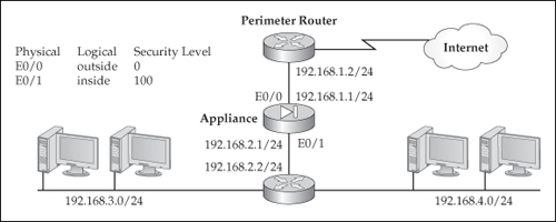
![]() I’ll first take a look at a simple NAT example, using the network shown in Figure 5-13. In this network, the appliance will perform NAT for any internal address (192.168.3.0/24 and 192.168.4.0/24). Here’s the NAT policy configuration for this example:
I’ll first take a look at a simple NAT example, using the network shown in Figure 5-13. In this network, the appliance will perform NAT for any internal address (192.168.3.0/24 and 192.168.4.0/24). Here’s the NAT policy configuration for this example:
ciscoasa(config)# nat-control
ciscoasa(config)# nat (inside) 1 0.0.0.0 0.0.0.0
ciscoasa(config)# global (outside) 1 200.200.200.10-200.200.200.254
                      netmask 255.255.255.0
![]() In this example, address translation is required (nat-control command). All of the devices off of the inside interface will have their source addresses translated to an address in the 200.200.200.0 subnet when exiting the outside interface. The addresses are dynamically assigned by the appliance by choosing unused ones in the pool.
In this example, address translation is required (nat-control command). All of the devices off of the inside interface will have their source addresses translated to an address in the 200.200.200.0 subnet when exiting the outside interface. The addresses are dynamically assigned by the appliance by choosing unused ones in the pool.
| Note | |
Interface PAT Example
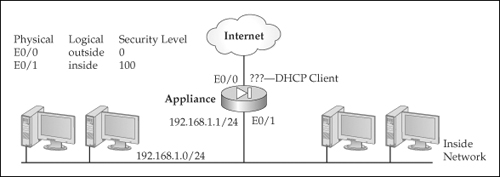
![]() I’ll use the network in Figure 5-14 to illustrate the configuration of a PAT policy using the appliance outside interface. Here’s the configuration:
I’ll use the network in Figure 5-14 to illustrate the configuration of a PAT policy using the appliance outside interface. Here’s the configuration:
ciscoasa(config)# nat-control
ciscoasa(config)# nat (inside) 1 0 0
ciscoasa(config)# global (outside) 1 interface
![]() This is a special example of PAT, where the appliance is using the outside interface IP address for the PAT address pool. This could be a static IP address on the interface or one dynamically assigned to the appliance using DHCP or PPPoE. In this example, the appliance is directly connected to the ISP and gets the outside interface address dynamically.
This is a special example of PAT, where the appliance is using the outside interface IP address for the PAT address pool. This could be a static IP address on the interface or one dynamically assigned to the appliance using DHCP or PPPoE. In this example, the appliance is directly connected to the ISP and gets the outside interface address dynamically.
NAT and PAT Example
![]() To illustrate the use of both NAT and PAT policies on an appliance, I’ll use the network shown previously in Figure 5-13. Here is the configuration:
To illustrate the use of both NAT and PAT policies on an appliance, I’ll use the network shown previously in Figure 5-13. Here is the configuration:
ciscoasa(config)# nat-control
ciscoasa(config)# nat (inside) 1 192.168.3.0 255.255.255.0
ciscoasa(config)# global (outside) 1 200.200.200.1-200.200.200.125
                      netmask 255.255.255.128
ciscoasa(config)# nat (inside) 2 192.168.4.0 255.255.255.0
ciscoasa(config)# global (outside) 2 200.200.200.126
                      netmask 255.255.255.255
![]() In this example, a combination of NAT and PAT is used for the internal devices: the two internal subnets are each assigned their own pool of public addresses:
In this example, a combination of NAT and PAT is used for the internal devices: the two internal subnets are each assigned their own pool of public addresses:
-
 For policy 1, 192.168.3.0/24 is translated to 200.200.200.1–125 (this uses NAT)
 -
 For policy 2, 192.168.4.0/24 is translated to 200.200.200.126 (this uses PAT)
PAT Example with Two Global Pools
![]() To illustrate the use of two global address pools on an appliance for one group of devices, I’ll use the network shown previously in Figure 5-13. Here is the configuration:
To illustrate the use of two global address pools on an appliance for one group of devices, I’ll use the network shown previously in Figure 5-13. Here is the configuration:
ciscoasa(config)# nat-control
ciscoasa(config)# nat (inside) 1 0.0.0.0 0.0.0.0
ciscoasa(config)# global (outside) 1 200.200.200.1
                      netmask 255.255.255.255
ciscoasa(config)# global (outside) 1 200.200.200.2
                      netmask 255.255.255.255
![]() This configuration performs PAT on all inside-to-outside connections by using the two addresses in the two global commands.
This configuration performs PAT on all inside-to-outside connections by using the two addresses in the two global commands.
| Note | |
PAT and Identity NAT Example
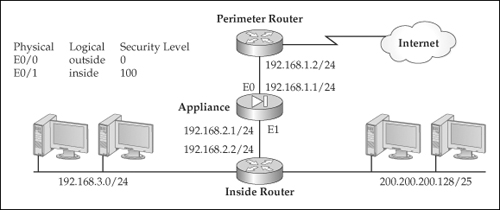
![]() To illustrate the use of PAT and Identity NAT on an appliance, I’ll use the network shown in Figure 5-15. In this example, I want to perform PAT for 192.168.3.0/24, but to perform no address translation on machines with an address from 200.200.200.128/25—the latter devices already have a public IP address. Here is the configuration:
To illustrate the use of PAT and Identity NAT on an appliance, I’ll use the network shown in Figure 5-15. In this example, I want to perform PAT for 192.168.3.0/24, but to perform no address translation on machines with an address from 200.200.200.128/25—the latter devices already have a public IP address. Here is the configuration:
ciscoasa(config)# nat-control
ciscoasa(config)# nat (inside) 0 200.200.200.128 255.255.255.128
ciscoasa(config)# nat (inside) 1 192.168.3.0 255.255.255.0 50 25
ciscoasa(config)# global (outside) 1 200.200.200.1
                      netmask 255.255.255.255
![]() In this example, the 192.168.3.0/24 subnet is translated to 200.200.200.1 using PAT when going from the inside interface to the outside, along with connection restrictions (50 complete and 25 embryonic connections). The 200.200.200.128/25 is excluded from translation between any interfaces.
In this example, the 192.168.3.0/24 subnet is translated to 200.200.200.1 using PAT when going from the inside interface to the outside, along with connection restrictions (50 complete and 25 embryonic connections). The 200.200.200.128/25 is excluded from translation between any interfaces.
Three-Interface NAT Example
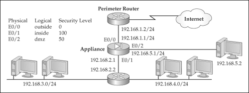
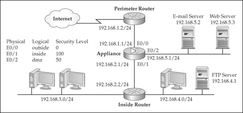
![]() With two interfaces, configuring translation policies is straightforward; adding interfaces complicates matters. Let’s look at an example to illustrate the complexity that three interfaces add to the situation. I’ll use the network shown in Figure 5-16. Here’s the configuration for the appliance:
With two interfaces, configuring translation policies is straightforward; adding interfaces complicates matters. Let’s look at an example to illustrate the complexity that three interfaces add to the situation. I’ll use the network shown in Figure 5-16. Here’s the configuration for the appliance:
ciscoasa(config)# nat-control
ciscoasa(config)# nat (inside) 1 0.0.0.0 0.0.0.0
ciscoasa(config)# nat (dmz) 1 192.168.5.0 255.255.255.0
ciscoasa(config)# global (outside) 1 200.200.200.10-200.200.200.254
                      netmask 255.255.255.0
ciscoasa(config)# global (dmz) 1 192.168.5.10-192.168.5.254
                      netmask 255.255.255.0
| Tip | |
![]() In this example, three interfaces are involved with address translation: inside, outside, and dmz. Here’s a breakdown of the address translation policies:
In this example, three interfaces are involved with address translation: inside, outside, and dmz. Here’s a breakdown of the address translation policies:
-
 inside-to-dmz This translation policy uses the nat command on the inside and the global command on the dmz interface (they both have a NAT ID of 1). Any traffic going from the inside interface to the dmz interface will be translated with NAT using the 192.168.5.10–192.168.5.254 range of addresses. Notice something interesting about the address pool for the DMZ segment: it has unused addresses from the 192.168.5.0/24 network. From the DMZ server perspective, the inside devices will look like they are physically connected to the DMZ, when in reality they are being translated. In the DMZ server ARP cache, the appliance MAC address for E0/2 would appear for the translated IP addresses, which means that if a DMZ server would ARP for a translated inside device, the appliance would respond back with its own MAC address on E0/2 (this process is referred to as proxy ARP).
 -
 inside-to-outside This translation policy uses the nat command on the inside and the global command on the outside interface (they both have a NAT ID of 1). Any traffic going from the inside interface to the outside interface will be translated with NAT using the 200.200.200.10–200.200.200.254 range of addresses.
 -
 dmz-to-outside This translation policy uses the nat command on the dmz and the global command on the outside interfaces (they both have a NAT ID of 1). Any traffic going from the inside interface to the outside interface will be translated with NAT using the 200.200.200.10–200.200.200.254 range of addresses. Notice that both the inside and dmz interfaces use the same global pool when accessing the outside network. This is a valid configuration; the only problem you might experience is that two sets of networks are sharing a limited pool of addresses.
| Tip | |
Policy NAT Example
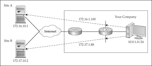
![]() The next example will show a simple configuration using Policy NAT, where the translation is controlled based on the destination the source is trying to reach. ACLs (discussed in Chapter 6) must be used in this situation. Here’s the configuration example, based on the network shown in Figure 5-17:
The next example will show a simple configuration using Policy NAT, where the translation is controlled based on the destination the source is trying to reach. ACLs (discussed in Chapter 6) must be used in this situation. Here’s the configuration example, based on the network shown in Figure 5-17:
ciscoasa(config)# access-list Site_A permit tcp 10.0.1.0 255.255.255.0
                      host 172.16.10.1
ciscoasa(config)# nat (inside) 100 access-list Site_A
ciscoasa(config)# global (outside) 100 172.16.1.100
                      netmask 255.255.255.255
ciscoasa(config)# access-list Site_B permit tcp 10.0.1.0 255.255.255.0
                      host 172.17.10.2
ciscoasa(config)# nat (inside) 101 access-list Site_B
ciscoasa(config)# global (outside) 101 172.17.1.88
                      netmask 255.255.255.255
![]() In the preceding example, any packets from 10.0.1.0/24 being sent to 172.16.10.1 are translated using PAT to an IP address of 172.16.1.100. If any packets from 10.0.1.0/24 are being sent to 172.17.10.2, however, they are translated, using PAT, to a different global address, 172.17.1.88. In this example, an ACL is used to control when address translation takes place: the source and destination involved in the connection.
In the preceding example, any packets from 10.0.1.0/24 being sent to 172.16.10.1 are translated using PAT to an IP address of 172.16.1.100. If any packets from 10.0.1.0/24 are being sent to 172.17.10.2, however, they are translated, using PAT, to a different global address, 172.17.1.88. In this example, an ACL is used to control when address translation takes place: the source and destination involved in the connection.
Policy Identity NAT Example
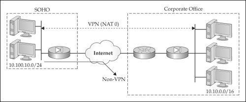
![]() The last dynamic translation policy I’ll show is based on the network in Figure 5-18. In this example, I’m configuring the appliance at the SOHO site, where traffic traversing the VPN to the Corporate site should be exempted from address translation (Identity NAT), and traffic going to the Internet should be translated using PAT. Here’s the configuration for the appliance:
The last dynamic translation policy I’ll show is based on the network in Figure 5-18. In this example, I’m configuring the appliance at the SOHO site, where traffic traversing the VPN to the Corporate site should be exempted from address translation (Identity NAT), and traffic going to the Internet should be translated using PAT. Here’s the configuration for the appliance:
SOHO(config)# access-list VPN-EXEMPT-NAT permit ip
                      10.100.10.0 255.255.255.0
                      10.10.0.0 255.255.0.0
SOHO(config)# nat-control
SOHO(config)# nat (inside) 0 access-list VPN-EXEMPT-NAT
SOHO(config)# nat (inside) 1 10.100.0.0 255.255.0.0
SOHO(config)# global (outside) 1 interface
![]() In the preceding example, the following translation policies are configured:
In the preceding example, the following translation policies are configured:
-
 When traffic goes across the site-to-site VPN tunnel to the Corporate office, it should not be translated: the access-list and nat (inside) 0 commands implement this policy.
 -
 When traffic goes from the SOHO to the Internet locations, it will be translated using PAT: the nat (inside) 1 and global (outside) 1 commands implement this policy.
 Configuring Static NAT Translation
![]() Static NAT translations are commonly used for inbound connections: you have a server on a higher-level interface that you want lower-level interface users to access, like Internet users accessing DMZ web, e-mail, and DNS servers. This section will discuss how to create a static NAT translation, and show a simple example of its usage.
Static NAT translations are commonly used for inbound connections: you have a server on a higher-level interface that you want lower-level interface users to access, like Internet users accessing DMZ web, e-mail, and DNS servers. This section will discuss how to create a static NAT translation, and show a simple example of its usage.
Static NAT Syntax
![]() To create a static NAT translation, use the following command:
To create a static NAT translation, use the following command:
ciscoasa(config)# static (local_if_name, global_if_name)
                      global_IP_addr local_IP_addr
                      [netmask subnet_mask]
                      [tcp [max_conns [embryonic_conn_limit]]
                      [udp max_conns [dns] [norandomseq]
![]() Of all the commands I’ve worked with on Cisco devices, the static command is the one I’ve most commonly seen misconfigured because of the order of the parameters: local interface, global interface, global IP address, and local IP address—notice that the local and global values don’t match up in a logical order!
Of all the commands I’ve worked with on Cisco devices, the static command is the one I’ve most commonly seen misconfigured because of the order of the parameters: local interface, global interface, global IP address, and local IP address—notice that the local and global values don’t match up in a logical order!
| Note | |
![]() Remember that translation policies always involve a pair of interfaces, as can be seen from the preceding syntax. The interface names are separated by a comma with no space. For outbound access, traffic entering the local interface with the specified local IP address (in the source IP address field of the IP packet) will be translated when leaving the global interface to the specified global IP address. For inbound access, traffic entering the global interface with a destination address that matches the global IP address in the static command will be translated to the local IP address and forwarded out the specified local interface.
Remember that translation policies always involve a pair of interfaces, as can be seen from the preceding syntax. The interface names are separated by a comma with no space. For outbound access, traffic entering the local interface with the specified local IP address (in the source IP address field of the IP packet) will be translated when leaving the global interface to the specified global IP address. For inbound access, traffic entering the global interface with a destination address that matches the global IP address in the static command will be translated to the local IP address and forwarded out the specified local interface.
![]() When configuring a static NAT translation, you can translate a single IP address, specifying a single local and global address with a 255.255.255.255 subnet mask value (this is the default), or you can configure what Cisco refers to as a net static, mapping one range of addresses in a network to a second network with the same range of addresses, like mapping 10.0.1.0/24 to 192.1.1.0/24, where 10.0.1.1 would map to 192.1.1.1, 10.0.1.2 would map to 192.1.1.2, and so on. With a net static, you need to configure the appropriate subnet mask value. The advantage of using a net static is that the appliance can now distinguish between host, network, and directed broadcast addresses for a network number, of which the appliance will not translate or forward the latter two.
When configuring a static NAT translation, you can translate a single IP address, specifying a single local and global address with a 255.255.255.255 subnet mask value (this is the default), or you can configure what Cisco refers to as a net static, mapping one range of addresses in a network to a second network with the same range of addresses, like mapping 10.0.1.0/24 to 192.1.1.0/24, where 10.0.1.1 would map to 192.1.1.1, 10.0.1.2 would map to 192.1.1.2, and so on. With a net static, you need to configure the appropriate subnet mask value. The advantage of using a net static is that the appliance can now distinguish between host, network, and directed broadcast addresses for a network number, of which the appliance will not translate or forward the latter two.
![]() The other parameters were discussed previously in the “Identifying Local Addresses for Translation” section.
The other parameters were discussed previously in the “Identifying Local Addresses for Translation” section.
| Tip | |
Static NAT Example
![]() To illustrate the configuration of static NAT translation policies, I’ll use the network shown in Figure 5-19. The following configuration shows the appliance configuration for both static NAT and dynamic NAT translation policies:
To illustrate the configuration of static NAT translation policies, I’ll use the network shown in Figure 5-19. The following configuration shows the appliance configuration for both static NAT and dynamic NAT translation policies:
ciscoasa(config)# nat-control
ciscoasa(config)# static (dmz,outside) 200.200.200.1 192.168.5.2
                      netmask 255.255.255.255
ciscoasa(config)# static (dmz,outside) 200.200.200.2 192.168.5.3
                      netmask 255.255.255.255
ciscoasa(config)# static (inside,outside) 200.200.200.3 192.168.4.1
                      netmask 255.255.255.255
ciscoasa(config)# nat (inside) 1 0.0.0.0 0.0.0.0
ciscoasa(config)# global (outside) 1 200.200.200.10-200.200.200.254
                      netmask 255.255.255.0
ciscoasa(config)# global (dmz) 1 192.168.5.10-192.168.5.254
                      netmask 255.255.255.0
![]() In this example, the appliance has three interfaces: inside, outside, and dmz. The first static command creates a static NAT translation policy for the DMZ public e-mail server: outside users send traffic to 200.200.200.1, which will be translated to 192.168.5.2 and forwarded to the dmz interface. The second static command creates a static NAT translation policy for the DMZ public web server: outside users send traffic to 200.200.200.2, which will be translated to 192.168.5.3 and forwarded to the dmz interface. The third static command creates a static NAT translation policy for the inside public FTP server: outside users send traffic to 200.200.200.3, which will be translated to 192.168.4.1 and forwarded to the inside interface.
In this example, the appliance has three interfaces: inside, outside, and dmz. The first static command creates a static NAT translation policy for the DMZ public e-mail server: outside users send traffic to 200.200.200.1, which will be translated to 192.168.5.2 and forwarded to the dmz interface. The second static command creates a static NAT translation policy for the DMZ public web server: outside users send traffic to 200.200.200.2, which will be translated to 192.168.5.3 and forwarded to the dmz interface. The third static command creates a static NAT translation policy for the inside public FTP server: outside users send traffic to 200.200.200.3, which will be translated to 192.168.4.1 and forwarded to the inside interface.
| Note | |
![]() There are two additional translation policies for outbound access. When inside users send traffic to the outside, the addresses will be translated, using NAT, to the address pool ranging from 200.200.200.10 to 200.200.200.254. Also, when inside users access the DMZ segment, the addresses will be translated to the address pool ranging from 192.168.5.10 to 192.168.5.254.
There are two additional translation policies for outbound access. When inside users send traffic to the outside, the addresses will be translated, using NAT, to the address pool ranging from 200.200.200.10 to 200.200.200.254. Also, when inside users access the DMZ segment, the addresses will be translated to the address pool ranging from 192.168.5.10 to 192.168.5.254.
 Configuring Static PAT Translation
![]() The appliances support static PAT, sometimes referred to as port address redirection (PAR). PAR is sometimes necessary when your ISP assigns you a single public IP address that you need to put on the outside interface of your appliance, but you want Internet users to access servers behind your appliance, like a web, DNS, and/or e-mail servers. Basically, PAR redirects traffic sent to one IP address and port number to a different IP address and, possibly, to a different port number. The following two sections will show you the syntax for configuring PAR as well as a simple example.
The appliances support static PAT, sometimes referred to as port address redirection (PAR). PAR is sometimes necessary when your ISP assigns you a single public IP address that you need to put on the outside interface of your appliance, but you want Internet users to access servers behind your appliance, like a web, DNS, and/or e-mail servers. Basically, PAR redirects traffic sent to one IP address and port number to a different IP address and, possibly, to a different port number. The following two sections will show you the syntax for configuring PAR as well as a simple example.
Static PAT Syntax
![]() The static command is used to redirect traffic from one destination address and destination port to a different internal machine (and possibly to a different destination port number). Here is the syntax of the command:
The static command is used to redirect traffic from one destination address and destination port to a different internal machine (and possibly to a different destination port number). Here is the syntax of the command:
ciscoasa(config)# static (local_if_name,global_if_name) {tcp | udp}
                      {global_IP_addr | interface}
                      global_dest_port_# local_IP_addr local_port_#
                      [netmask subnet_mask]
                      [tcp [max_TCP_conns [embryonic_conn_limit]]
                      [udp max_UDP_conns [dns] [norandomseq]
![]() For port redirection, specify the IP protocol: tcp or udp. The global_IP_addr is the global/public IP address that the outside world sends traffic to. Instead of using this address, you can specify the interface parameter, which will have the appliance use the address assigned to the global_if_name interface. The global port number is the port number of the application that the external device is trying to reach, like 21 for FTP.
For port redirection, specify the IP protocol: tcp or udp. The global_IP_addr is the global/public IP address that the outside world sends traffic to. Instead of using this address, you can specify the interface parameter, which will have the appliance use the address assigned to the global_if_name interface. The global port number is the port number of the application that the external device is trying to reach, like 21 for FTP.
![]() The local_IP_address is the actual IP address assigned to the internal device, and the local_port_# is the port number the application is listening to on the internal device. The other parameters were discussed previously in the “Identifying Local Addresses for Translation” section.
The local_IP_address is the actual IP address assigned to the internal device, and the local_port_# is the port number the application is listening to on the internal device. The other parameters were discussed previously in the “Identifying Local Addresses for Translation” section.
Static PAT Example
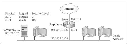
![]() To illustrate the configuration of static PAT or PAR translation policies, I’ll use the network shown in Figure 5-20. The following configuration shows the appliance configuration for PAR:
To illustrate the configuration of static PAT or PAR translation policies, I’ll use the network shown in Figure 5-20. The following configuration shows the appliance configuration for PAR:
ciscoasa(config)# static (inside,outside) tcp interface 80
                      192.168.1.20 80 netmask 255.255.255.255
![]() In this example, web traffic sent to port 80 to the IP address on the outside interface of the appliance will be redirected to 192.168.1.20 on port 80 of the inside interface.
In this example, web traffic sent to port 80 to the IP address on the outside interface of the appliance will be redirected to 192.168.1.20 on port 80 of the inside interface.
 Finding a Matching Translation Policy
![]() An address translation is configured for every source and destination interface pair: this allows the appliance to translate a source address to something different depending on the destination interface the source is trying to reach. When address translation is required (NAT control is enabled), there must be an existing entry in the xlate table, or the appliance must be able to build an entry before the appliance will switch a packet between interfaces: Building translation policies can be done dynamically (nat and global commands) or statically (static command). The exceptions to this rule are the nat 0 commands, which create exemptions to the address translation process.
An address translation is configured for every source and destination interface pair: this allows the appliance to translate a source address to something different depending on the destination interface the source is trying to reach. When address translation is required (NAT control is enabled), there must be an existing entry in the xlate table, or the appliance must be able to build an entry before the appliance will switch a packet between interfaces: Building translation policies can be done dynamically (nat and global commands) or statically (static command). The exceptions to this rule are the nat 0 commands, which create exemptions to the address translation process.
![]() However, when multiple translation policies are configured, the question is which translation policy should be used by the appliance. When looking for a matching translation policy, the appliance goes through the following steps:
However, when multiple translation policies are configured, the question is which translation policy should be used by the appliance. When looking for a matching translation policy, the appliance goes through the following steps:
-
 The appliance looks for an existing translation in the translation table; sometimes Cisco will refer to this as trying to find a “matching xlate slot” in the translation table.
 -
 If no entry exists in the translation table, the appliance looks for address translation exceptions in the nat 0 commands on a best-match basis.
 -
 If there are no matches on the Identity NAT commands, the appliance will try to find a match against the configured static NAT commands based on a best-match basis.
 -
 If there are no matches on the static NAT commands, the appliance will try to find a match against the configured static PAT (PAR) policies on a best-match basis.
 -
 If no match is found within the PAR translation policies, the appliance then looks for a match in its policy nat and global commands with a corresponding ACL.
 -
 If there is not a match on a policy translation configuration, the appliance then looks for a match in its normal nat and global commands.
 -
 If a translation or translation policy doesn’t exist for the packet, the appliance will drop the packet if NAT control is enabled; if NAT control is not enabled, then the packet is not translated, but can flow through the appliance, assuming other appliance policies allow it.

