Overview
This chapter will introduce one of the advanced features that has been supported on the appliances for quite some time: failover. Failover provides redundancy between appliances, so if one appliance fails, you can have a redundant appliance take over for the failed one. The topics discussed in this chapter include
-
An introduction to failover, including the failover types, hardware, software, and license requirements, failover restrictions, and software upgrades
-
The two implementations of failover: active/standby and active/active
-
Cabling the appliances that will participate in failover
-
How appliances communicate with each other about failover, how they detect problems, and when failover can occur
-
Configuring active/standby failover
-
Configuring active/active failover
Failover Requirements
![]() To implement failover, you have to have the correct appliances and the appropriate licensing, and to match up the hardware and software on the units. The following sections will discuss these items in more depth.
To implement failover, you have to have the correct appliances and the appropriate licensing, and to match up the hardware and software on the units. The following sections will discuss these items in more depth.
Supported Models
![]() Not all appliances support failover. All the ASAs support failover; however, the ASA 5505 doesn’t support active/active failover (see the “Failover Implementations” section). Of the PIXs, only the 515s and higher support failover. The Firewall Services Module (FWSM) also supports failover.
Not all appliances support failover. All the ASAs support failover; however, the ASA 5505 doesn’t support active/active failover (see the “Failover Implementations” section). Of the PIXs, only the 515s and higher support failover. The Firewall Services Module (FWSM) also supports failover.
| Note |
|
Hardware, Software, and Configuration Requirements
![]() For the hardware between the two appliances, the only thing that doesn’t have to be the same is the flash memory size—all other components must be the same. For example, you could use two 5510s, but not a 5510 and a 5520. You could use two ASA 5540s, but not if one had an IPS card and the other didn’t. Basically, with the exception of flash, the hardware between the two units must be identical: same models, same interfaces and cards, same amount of RAM, and so on.
For the hardware between the two appliances, the only thing that doesn’t have to be the same is the flash memory size—all other components must be the same. For example, you could use two 5510s, but not a 5510 and a 5520. You could use two ASA 5540s, but not if one had an IPS card and the other didn’t. Basically, with the exception of flash, the hardware between the two units must be identical: same models, same interfaces and cards, same amount of RAM, and so on.
![]() If you had PIXs running version 6 or earlier, the two PIXs in failover had to be running the same OS image and the same PIX Device Manager (PDM) image. (ASDM is the replacement for PDM and is discussed in Chapter 27.) For example, if one PIX were running version 6.3(4) and the other were running 6.3(5), failover wouldn’t work—they would have to be running exactly the same version of software in version 6 and earlier. Starting in version 7, Cisco slightly loosened the software requirements: the minor releases had to match up, but not subreleases within a minor release. For example, if one appliance were running 7.1(1) and the other 7.1(2), the two appliances could participate in failover; however, if one were running 7.0(4) and the other were running 7.1(2), failover would fail.
If you had PIXs running version 6 or earlier, the two PIXs in failover had to be running the same OS image and the same PIX Device Manager (PDM) image. (ASDM is the replacement for PDM and is discussed in Chapter 27.) For example, if one PIX were running version 6.3(4) and the other were running 6.3(5), failover wouldn’t work—they would have to be running exactly the same version of software in version 6 and earlier. Starting in version 7, Cisco slightly loosened the software requirements: the minor releases had to match up, but not subreleases within a minor release. For example, if one appliance were running 7.1(1) and the other 7.1(2), the two appliances could participate in failover; however, if one were running 7.0(4) and the other were running 7.1(2), failover would fail.
![]() Another software requirement on the appliances is that the same licensed features must be enabled on both appliances. If one appliance only has a DES license and the other has a DES/3DES/AES license, failover won’t work. Likewise, if one appliance has a 5-context license and the other has a 50-context license, again, failover won’t work.
Another software requirement on the appliances is that the same licensed features must be enabled on both appliances. If one appliance only has a DES license and the other has a DES/3DES/AES license, failover won’t work. Likewise, if one appliance has a 5-context license and the other has a 50-context license, again, failover won’t work.
![]() The configurations on the appliances must be basically the same, with the exception of the IP and MAC addresses and the unit type used by the two appliances. The unit types are primary and secondary, and these don’t change when a failover occurs. At least you don’t have to manually synchronize the configurations between the two appliances: you’ll make your changes on the active appliance in the failover pair, and the configuration change will automatically be replicated to the other appliance.
The configurations on the appliances must be basically the same, with the exception of the IP and MAC addresses and the unit type used by the two appliances. The unit types are primary and secondary, and these don’t change when a failover occurs. At least you don’t have to manually synchronize the configurations between the two appliances: you’ll make your changes on the active appliance in the failover pair, and the configuration change will automatically be replicated to the other appliance.
License Requirements
![]() If you have an ASA 5505 or 5510, you need the Security Plus license to implement failover. The 5520s and higher don’t require any special licensing. The PIXs, on the other hand, are a bit more complicated with their licensing. The PIXs that support failover (the 515s and higher) support three kinds of general licenses: restricted (R), unrestricted (UR), and failover (FO).
If you have an ASA 5505 or 5510, you need the Security Plus license to implement failover. The 5520s and higher don’t require any special licensing. The PIXs, on the other hand, are a bit more complicated with their licensing. The PIXs that support failover (the 515s and higher) support three kinds of general licenses: restricted (R), unrestricted (UR), and failover (FO).
![]() A PIX restricted license restricts the amount of RAM and the number of interfaces the PIX can use, as well as failover. An unrestricted license supports the maximum amount of RAM and interfaces the PIX model supports, as well as allowing for the use of failover. Obviously there is a price difference between the two. When Cisco sold the PIXs, a 515E with a restricted license, for example, might cost $3,000 US, while the same unit with an unrestricted license would cost over $6,000 US. One complaint customers had about the licensing had to do with failover. Back in version 6 and earlier, only one implementation of failover was available: active/standby. As you’ll see later in the chapter, with this implementation, the active unit processes traffic, and the other waits until the active unit fails, and then this standby unit will start processing traffic. In other words, the standby unit will only process traffic if the active unit fails ... which might be never!
A PIX restricted license restricts the amount of RAM and the number of interfaces the PIX can use, as well as failover. An unrestricted license supports the maximum amount of RAM and interfaces the PIX model supports, as well as allowing for the use of failover. Obviously there is a price difference between the two. When Cisco sold the PIXs, a 515E with a restricted license, for example, might cost $3,000 US, while the same unit with an unrestricted license would cost over $6,000 US. One complaint customers had about the licensing had to do with failover. Back in version 6 and earlier, only one implementation of failover was available: active/standby. As you’ll see later in the chapter, with this implementation, the active unit processes traffic, and the other waits until the active unit fails, and then this standby unit will start processing traffic. In other words, the standby unit will only process traffic if the active unit fails ... which might be never!
![]() To make customers happy, Cisco created a third license for the PIXs, called a Failover (FO) license. The FO license is meant for a standby unit, and it costs about the same, if not a little bit less, than a restricted license. An FO license has all the same features and capabilities as the UR license. One concern Cisco had about the FO license is that they didn’t want customers buying a PIX with the FO license and running it as a stand-alone unit or pairing two FO licensed PIXs together—Cisco wanted their customers to buy the appropriate license based on their needs. Therefore, the PIXs won’t let two FO licensed devices work with failover. Likewise if an FO licensed PIX boots up and doesn’t see a failover mate with a UR license, at least once every 24 hours the FO licensed PIX will reboot itself. However, if the FO unit boots up and sees its primary mate, and the primary mate fails, the FO unit will not perform the random reboot process. This ensures that customers don’t try to run the FO license in a stand-alone configuration since rebooting obviously creates disruption for company traffic.
To make customers happy, Cisco created a third license for the PIXs, called a Failover (FO) license. The FO license is meant for a standby unit, and it costs about the same, if not a little bit less, than a restricted license. An FO license has all the same features and capabilities as the UR license. One concern Cisco had about the FO license is that they didn’t want customers buying a PIX with the FO license and running it as a stand-alone unit or pairing two FO licensed PIXs together—Cisco wanted their customers to buy the appropriate license based on their needs. Therefore, the PIXs won’t let two FO licensed devices work with failover. Likewise if an FO licensed PIX boots up and doesn’t see a failover mate with a UR license, at least once every 24 hours the FO licensed PIX will reboot itself. However, if the FO unit boots up and sees its primary mate, and the primary mate fails, the FO unit will not perform the random reboot process. This ensures that customers don’t try to run the FO license in a stand-alone configuration since rebooting obviously creates disruption for company traffic.
| Note |
|
 Failover Restrictions
![]() When using failover, certain restrictions apply. For example, the following addressing is currently unsupported on appliances participating in failover:
When using failover, certain restrictions apply. For example, the following addressing is currently unsupported on appliances participating in failover:
-
 DHCP client
 -
 PPPoE client
 -
 IPv6 addressing
![]() Another restriction is that if you will be implementing active/active failover, which requires the use of contexts, VPNs of any type are unsupported. And even with active/standby failover, if the failover pair involves ASA 5505s and they’re configured as Easy VPN remotes, failover will not function.
Another restriction is that if you will be implementing active/active failover, which requires the use of contexts, VPNs of any type are unsupported. And even with active/standby failover, if the failover pair involves ASA 5505s and they’re configured as Easy VPN remotes, failover will not function.
Failover Implementations
![]() In the last few sections I’ve mentioned the terms “active/standby” and “active/active failover.” These are the two implementations that Cisco supports for failover. Through version 6 of the OS, only active/standby was supported, with active/active support being added in version 7. The following sections will discuss these two failover implementations as well as how addressing (IP and MAC) of the units is implemented in either of the two implementations.
In the last few sections I’ve mentioned the terms “active/standby” and “active/active failover.” These are the two implementations that Cisco supports for failover. Through version 6 of the OS, only active/standby was supported, with active/active support being added in version 7. The following sections will discuss these two failover implementations as well as how addressing (IP and MAC) of the units is implemented in either of the two implementations.
 Active/Standby Failover
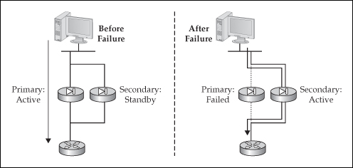
![]() The active/standby implementation of failover has two appliances: primary and secondary. By default the primary unit performs the active role, and the secondary the standby role. Only one unit, the active appliance, will process traffic between interfaces, as can be seen in the left side of Figure 23-1. With few exceptions, all configuration changes are made on the active unit and are then synchronized with the standby unit. The standby appliance serves as a hot standby or backup of the active unit. It does not pass traffic between interfaces. Its main responsibility is to monitor the active unit and promote itself to the active role if the active unit can no longer do this, as can be seen in the right side of Figure 23-1.
The active/standby implementation of failover has two appliances: primary and secondary. By default the primary unit performs the active role, and the secondary the standby role. Only one unit, the active appliance, will process traffic between interfaces, as can be seen in the left side of Figure 23-1. With few exceptions, all configuration changes are made on the active unit and are then synchronized with the standby unit. The standby appliance serves as a hot standby or backup of the active unit. It does not pass traffic between interfaces. Its main responsibility is to monitor the active unit and promote itself to the active role if the active unit can no longer do this, as can be seen in the right side of Figure 23-1.
 Addressing and Failover
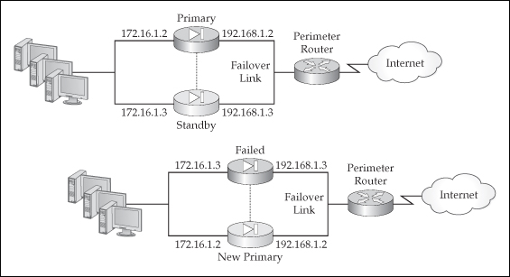
![]() Each appliance (or context) participating in failover needs unique addresses—IP and MAC—for each subnet it is connected to, which can be seen in the top-left side of Figure 23-2. If a failover occurs, the current standby unit promotes itself to the active role and changes its IP and MAC addresses to match those of the primary, as can be seen in the bottom-right side of Figure 23-2. The new active appliance then sends out frames on each interface to update any connected switch MAC address table. Note that the failed appliance will not become a standby unit unless the problem that caused the failover is fixed. When the problem is fixed, the previously active unit will come back online in a standby state and assume the IP and MAC addresses of the original standby unit. In active/standby failover, there is no preemption process; however, in active/active failover, preemption is optional. This somewhat makes sense because performing any kind of cutover can create disruptions for traffic.
Each appliance (or context) participating in failover needs unique addresses—IP and MAC—for each subnet it is connected to, which can be seen in the top-left side of Figure 23-2. If a failover occurs, the current standby unit promotes itself to the active role and changes its IP and MAC addresses to match those of the primary, as can be seen in the bottom-right side of Figure 23-2. The new active appliance then sends out frames on each interface to update any connected switch MAC address table. Note that the failed appliance will not become a standby unit unless the problem that caused the failover is fixed. When the problem is fixed, the previously active unit will come back online in a standby state and assume the IP and MAC addresses of the original standby unit. In active/standby failover, there is no preemption process; however, in active/active failover, preemption is optional. This somewhat makes sense because performing any kind of cutover can create disruptions for traffic.
| Note |
|
 Active/Active Failover
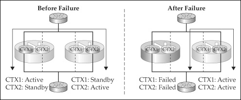
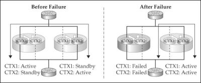
![]() In the active/active implementation of failover, both appliances in the failover pair process traffic. To accomplish this, two contexts are needed, as is depicted in the right side of Figure 23-3. On the left appliance, CTX1 performs the active role and CTX2 the standby role—the roles are reversed for the two contexts on the other appliance. Then, static routes on the connected routers are used to load-balance traffic between the two contexts, assuming they are running in routed mode. If the contexts are running in transparent mode, then the connected routers could use a dynamic routing protocol to learn of the two equal-cost paths through the contexts to the routers on the other side.
In the active/active implementation of failover, both appliances in the failover pair process traffic. To accomplish this, two contexts are needed, as is depicted in the right side of Figure 23-3. On the left appliance, CTX1 performs the active role and CTX2 the standby role—the roles are reversed for the two contexts on the other appliance. Then, static routes on the connected routers are used to load-balance traffic between the two contexts, assuming they are running in routed mode. If the contexts are running in transparent mode, then the connected routers could use a dynamic routing protocol to learn of the two equal-cost paths through the contexts to the routers on the other side.
| Note |
|
Failover Cabling
![]() Two types of connections can be used for failover:
Two types of connections can be used for failover:
-
 Failover cable or link
 -
 Stateful cable or link
![]() The following sections will discuss the differences between these two types of cables or links, as well as how to cable up the appliances.
The following sections will discuss the differences between these two types of cables or links, as well as how to cable up the appliances.
 Failover Link
![]() The failover link is used to replicate appliance commands and to share information about the status of failover between the failover pair. This link must be a dedicated connection between the two appliances, where no user traffic is allowed. There are two kinds of failover links:
The failover link is used to replicate appliance commands and to share information about the status of failover between the failover pair. This link must be a dedicated connection between the two appliances, where no user traffic is allowed. There are two kinds of failover links:
-
 Serial
 -
 LAN-based failover (LBF)
Serial Cable
![]() The serial cable method of connecting the appliances is only supported on the PIXs. The serial cable is a Cisco proprietary RS-232 cable, clocked at 115 Kbps, with DB-15 connectors. The PIX 515s and higher come with this serial interface installed. One end of the cable is marked “primary,” which connects to the primary unit, and the other is marked “secondary.” If you purchased the PIXs in a failover bundle, where one has a UR and the other an FO license, the UR-licensed appliance needs to be connected to the primary end of the cable, and the FO-licensed appliance to the secondary end.
The serial cable method of connecting the appliances is only supported on the PIXs. The serial cable is a Cisco proprietary RS-232 cable, clocked at 115 Kbps, with DB-15 connectors. The PIX 515s and higher come with this serial interface installed. One end of the cable is marked “primary,” which connects to the primary unit, and the other is marked “secondary.” If you purchased the PIXs in a failover bundle, where one has a UR and the other an FO license, the UR-licensed appliance needs to be connected to the primary end of the cable, and the FO-licensed appliance to the secondary end.
![]() The maximum length of the cable is 2–3 meters, so one main disadvantage of using this cabling method is that the two appliances must be physically close to each other. The main advantage of using the serial cable, however, compared with LBF, is that one of the pin-outs on the serial cable is power. If one of the units loses power, the other will immediately notice this.
The maximum length of the cable is 2–3 meters, so one main disadvantage of using this cabling method is that the two appliances must be physically close to each other. The main advantage of using the serial cable, however, compared with LBF, is that one of the pin-outs on the serial cable is power. If one of the units loses power, the other will immediately notice this.
LAN-Based Failover Cable
![]() LBF was introduced in version 6.2. LBF uses one of the Ethernet interfaces on the appliance to communicate with its mate. Cisco uses a proprietary IP protocol for the communications, where both appliances will need IP addresses on the LBF interface to communicate with each other. This interface must be dedicated to failover—it cannot be used for data functions; however, you could easily set up a trunk connection on an interface, where one VLAN would be dedicated to failover communications and other VLANs for data communications.
LBF was introduced in version 6.2. LBF uses one of the Ethernet interfaces on the appliance to communicate with its mate. Cisco uses a proprietary IP protocol for the communications, where both appliances will need IP addresses on the LBF interface to communicate with each other. This interface must be dedicated to failover—it cannot be used for data functions; however, you could easily set up a trunk connection on an interface, where one VLAN would be dedicated to failover communications and other VLANs for data communications.
![]() Cisco originally designed LBF for companies that do not want to place the paired appliances physically close to each other. For example, if you have a campus network and the building the appliances are in loses power, failover doesn’t do you any good; however, if you could place the appliances in different buildings, when one building loses power, you still have an appliance in the second building that can process traffic. And since you can use fiber to connect the appliances in the two buildings (this would require a copper-to-fiber transceiver for RJ-45 Ethernet interfaces), the buildings could be separated by a few kilometers.
Cisco originally designed LBF for companies that do not want to place the paired appliances physically close to each other. For example, if you have a campus network and the building the appliances are in loses power, failover doesn’t do you any good; however, if you could place the appliances in different buildings, when one building loses power, you still have an appliance in the second building that can process traffic. And since you can use fiber to connect the appliances in the two buildings (this would require a copper-to-fiber transceiver for RJ-45 Ethernet interfaces), the buildings could be separated by a few kilometers.
![]() Given its advantages, LBF does have two limitations: first, unlike the serial cable, LBF cannot directly detect that a mated pair has lost power—it must use keepalives to detect this (which is discussed later in the “Failover Operation” section). Therefore, failover will take a little bit longer to occur in this situation. Second, certain kinds of failures cannot be detected if a crossover cable is used to connect the two appliances. For example, when you’re using a crossover cable and directly connecting the two appliances together, if an interface failure occurs on the failover link, the two appliances will be unable to determine which of the two interfaces is causing the problem. Actually, in version 6, you couldn’t use a crossover cable; this has been added in version 7. Cisco recommends that you connect the appliances together either via a switch, where the failover connection is in its own VLAN, or via a hub.
Given its advantages, LBF does have two limitations: first, unlike the serial cable, LBF cannot directly detect that a mated pair has lost power—it must use keepalives to detect this (which is discussed later in the “Failover Operation” section). Therefore, failover will take a little bit longer to occur in this situation. Second, certain kinds of failures cannot be detected if a crossover cable is used to connect the two appliances. For example, when you’re using a crossover cable and directly connecting the two appliances together, if an interface failure occurs on the failover link, the two appliances will be unable to determine which of the two interfaces is causing the problem. Actually, in version 6, you couldn’t use a crossover cable; this has been added in version 7. Cisco recommends that you connect the appliances together either via a switch, where the failover connection is in its own VLAN, or via a hub.
 Stateful Link
![]() The stateful link, if stateful failover is enabled, is used to replicate state information between the appliances, like the conn and xlate tables, among other things. The state link must be an Ethernet interface; on the PIXs, you can’t use the serial interface. Because of the amount of information that might have to be replicated, Cisco recommends that you don’t use a data interface for this function. Either use a dedicated interface or, if you are using LBF, have both LBF and the state information run on the same interface.
The stateful link, if stateful failover is enabled, is used to replicate state information between the appliances, like the conn and xlate tables, among other things. The state link must be an Ethernet interface; on the PIXs, you can’t use the serial interface. Because of the amount of information that might have to be replicated, Cisco recommends that you don’t use a data interface for this function. Either use a dedicated interface or, if you are using LBF, have both LBF and the state information run on the same interface.
 PIX Cabling
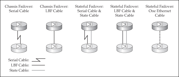
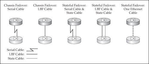
![]() Now that you understand the two kinds of links—failover and state—let’s discuss how you cable up the appliances. I’ll start with the PIXs first, which is illustrated in Figure 23-4. As you can see, you have a lot of options. Without a stateful link, only hardware or chassis redundancy is provided. For PIXs located close to each other, I would recommend using the serial cable for the failover link. For units that are more than 3 meters apart, and if you also need to implement stateful failover, I would use the option listed on the right side of Figure 23-4, where both the failover and stateful links share the same interface.
Now that you understand the two kinds of links—failover and state—let’s discuss how you cable up the appliances. I’ll start with the PIXs first, which is illustrated in Figure 23-4. As you can see, you have a lot of options. Without a stateful link, only hardware or chassis redundancy is provided. For PIXs located close to each other, I would recommend using the serial cable for the failover link. For units that are more than 3 meters apart, and if you also need to implement stateful failover, I would use the option listed on the right side of Figure 23-4, where both the failover and stateful links share the same interface.
| Note |
|
 ASA Cabling
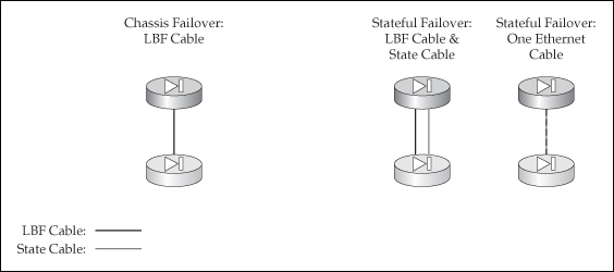
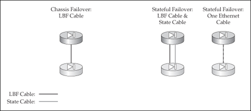
![]() Because the ASAs don’t have a serial interface, only Ethernet connections can be used, which means that you must use LBF. So as you can see in Figure 23-5, you have fewer options than with the PIXs. As with the PIXs, though, if you are also implementing stateful failover, I recommend that you use the same Ethernet interface for each.
Because the ASAs don’t have a serial interface, only Ethernet connections can be used, which means that you must use LBF. So as you can see in Figure 23-5, you have fewer options than with the PIXs. As with the PIXs, though, if you are also implementing stateful failover, I recommend that you use the same Ethernet interface for each.

