Networks have become more complex, interactive, mission-critical, and costly. Keeping track of network elements being installed, monitoring the way they interact with multiple technologies, and scrutinizing the overall changes occurring in the network is very difficult. Because networks are expected to be available at all times and operate flawlessly, their managers need to know when these expectations are not going to be met. They also need to justify deployment costs and validate assumptions before new systems are operational. As a result, analyzing and monitoring of functions of new and existing network technologies has become crucial.
This ReferencePoint focuses on network traffic analysis, explaining the Multi-Router Traffic Grapher (MRTG) and its architecture as well as how to install and configure it.
Network Analysis and Monitoring
This involves capturing, filtering, decoding, and organizing observations about the functioning of a network service. Facilities that provide network services and components that make up a communication facility are also tracked. Monitoring and analysis provide feedback on network availability and reliability, thereby helping to preempt failure by taking corrective action when necessary.
Aspects of Network Analysis
A successful network analysis and monitoring system must provide information needed to plan, organize, control, implement, operate, and administer the network. The main goal is to detect service-threatening conditions, such as network choking because of heavy usage, before they become visible to the end user. Some of the end uses of online network analysis systems include:
-
Detecting changes in node activities, end user access, network topology, and status and performance ratings
-
Debugging network problems
-
Finding out who is using the maximum bandwidth and whether the person is authorized to do so
-
Identifying and alerting management about service outages, degrading performance, and component faults
-
Monitoring network interfaces for communication problems
-
Maintaining and keeping track of event histories, trends, and loading statistics
-
Online simulation and capture of live traffic analysis
If monitoring and analysis were not part of the system, network evaluation would be labor-intensive and reactive, network traffic capacity planning would be impossible, the quality of service could not be regulated, security could be breached and the breaches remain undetected, and unplanned service disruptions could occur.
Techniques for Network Monitoring and Analysis
Monitoring can be done online while user traffic is on the network, or offline while only test messages are flowing, or under both conditions.
When networks are out of service, test sequences are generated and the results are monitored and analyzed to determine measurable levels of performance and protocol conformance. These tests can be conducted in a test environment, or in a network operations center, or during outage in an operational network.
Online monitoring and analysis can be scheduled at different times of the day, or invoked when circumstances, such as load changes or quality concerns, demand a closer scrutiny.
Continuous Monitoring
This is also called intrusive testing and is the most costly method, in resources and time, of monitoring a network. A very large number of access points dedicated to the monitoring system may be required. The amount of data collected and transported to a remote database can be very high. This technique makes proactive management and dynamic recovery of the network a reality. It offers a complete solution to network monitoring and analyses. The number of points of observation, the frequency of polling, and the degree of summarization performed at the source is best.
Scheduled Monitoring
This, along with filtering, reduces cost because the monitoring functions are executed only at certain times. For example, a network can be monitored during peak hours alone or at a specific subset of the location at set times. This reduces the volume of data collected and the amount of processing required. A variety of scheduling strategies, such as Random testing, Regular polling, and Responding to user requests, can be applied to a system. On the downside, there is the possibility of missing an important event. Some uncertainty occurs when the test points are not event driven.
Filtering data before monitoring helps selectively trap events and errors. Data can be filtered during test stages, implementation turn-up, and operational maintenance.
Reactive Monitoring
This is performed in reaction to an outage or network performance failure, in which monitoring is only turned on when a trouble ticket is opened. The end user generally triggers the mechanism by complaining about network performance.
Although the number of simultaneous test points is relatively low in reactive monitoring, it is difficult to geographically coordinate and correlate the tests. By implementing a remote diagnostic monitoring system, such as a protocol analyzer, reactive monitoring can be activated before performance failures. This minimizes system and personnel cost. The reactive approach can be used in medium to large, priority, or shared networks.
Data Collection
The data collected by the network monitoring system can be captured on hard disk or floppy disk, or it can be transferred to a central database management system immediately. The data can be filtered, edited, and kept for subsequent uploading, or analyzed at the point of capture so that the results alone are forwarded to the control center. If the monitoring function directly controls the network, much of the data need not be transferred at all because it is used proactively at the control point. All the collected data must be defined and understood if data correlation across multiple events and locations is to be achieved.
Network Analysis and Monitoring Systems Architecture
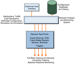
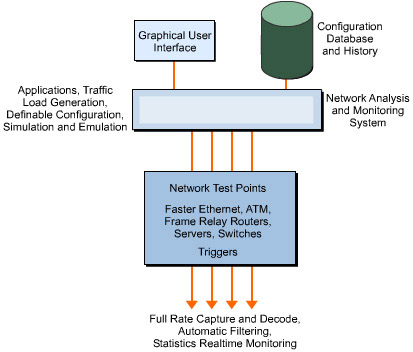
A number of basic functions must be included in any monitoring and analysis systems architecture. These are shown in Figure 4-9-1:
The network monitoring and analysis system is a flexible application. It is like any distributed system in its requirements. The network monitoring and analysis system can be based on a set of processing resources or may be integrated into the network. The key features of any monitoring and analysis system are:
-
Network access test points
-
Network capture and filtering processing
-
Data repository histograms and statistical reports
-
Intuitive user interface for quick response
-
Traffic generator
The architecture depends on what needs to be monitored, filtered, and captured. Major architectural decisions to be made during network planning include:
-
Centralized versus distributed processing. Network test points are, by definition, distributed.
-
Portable versus embedded applications for monitoring and analysis.
-
Continuous versus connect-and-look modes of data collection.
-
Wireline speed versus store-and-process modes of operation.
-
Larger buffer capacity for report generation.
-
Proactive versus reactive management techniques.
-
Protocol or wireline versus component or node hardware and software monitoring.
-
Functional versus performance monitoring.
-
Monitoring of user versus test traffic in live or test bed situations.
-
Standards-based versus product-specific monitoring.
Hardware versus Software
Hardware tools are mostly reactive. When a problem occurs, the tool is plugged into the network point and monitored. This provides limited access to the network and is suitable where the basic problem relates to interference among end users, for example, congestion or protocol errors. Software-based tools can observe a large number of points in the network either continuously or on command, without manual intervention.
Network Points to be Monitored for Traffic Analysis
In layered network architecture, the services provided by one layer support the needs of the layer above it. Each layer represents a set of unique functions and protocols. A network monitoring and analysis system must have access to and understand the protocol messages of each level.
The hub is a key element in monitoring traffic. Hubs provide the first point of contact for an end system attached to a network and serve as an observation point from which to examine data flow.
Another critical network element is the router, which is used to connect logically separated networks. Monitoring and analysis of the routers and the routing process provide information about the network.
Gateways, which interconnect applications that are not directly compatible and help conversion between different protocol suites, are also eligible for monitoring.
Elements of an Efficient Network Monitoring and Analysis System
Elements of an efficient system for monitoring and analyzing networks include:
-
An intuitive graphical user interface
-
Automated processes, detection mechanisms, and measurements
-
Comprehensive operations and management analyses
-
A common and consistent command language
-
Simultaneous support for multiple technologies
-
Remote access, via network connections, to test points
-
Open system platform
-
Real-time operation for multiple points of attachment and a wide range of network speeds
MRTG
In 1994, Tobias Oetiker and his team, working on a 64-kbit line whose performance required monitoring, wrote the first MRTG program. The program created a constantly updated graph on the Web, showing the traffic load on the Internet link. The present day MRTG is an improved version, in which programming has been done in Perl and C. Although many free tools for network traffic analysis are available on the Web, MRTG’s ability to produce long-term analysis and it is easily decipherable presentation have made it a widely accepted tool.
MRTG uses the Simple Network Management Protocol (SNMP) to gather information from network devices. The output of MRTG is generated in the form of HTML code and GIF images and can be used for continuous monitoring of network traffic. Along with a detailed daily view, MRTG creates graphic representations that depict network traffic for as much as a year. This is possible because MRTG keeps a log of all data pulled from the router. Because the log is automatically updated and consolidated, it does not grow voluminous. The log contains all the relevant data for traffic witnessed during the previous two years.
SNMP
SNMP, which defines the way all devices are managed over all networks, is widely accepted in LAN environments. The network administrator can monitor the health of all network components in a LAN or WAN from a central point through this common interface. SNMP provides guidelines for information collection, information structure, and message transmission to and from the network device. Many peripheral components may share the characteristics of interfacing to the protocol, such as printers and UPSs, while certain components have their won unique set of communication rules. The information gathered by these network devices is sent to a database, called a Management Information Base (MIB). The operating system software uses an SNMP management software subroutine to collect the contents of each MIB and compile it into a decipherable format. This information is then sent to the master network console for analysis.
MRTG has a Perl script that uses SNMP to read the traffic counters of the routers and a C program that logs the traffic data and creates graphs for the traffic movement on the monitored network connection. These graphs are embedded into Web pages, which can be viewed from a Web browser.
MRTG Architecture Overview
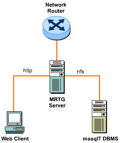
Figure 4-9-2 shows the working of an MRTG Server:
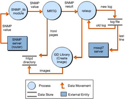
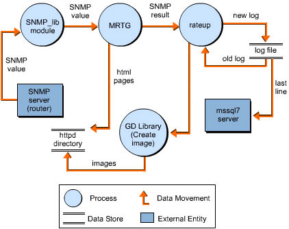
Figure 4-9-3 shows the flow of data in MRTG internal processes:
| Note | The use of the MSSQL Server 7 is not mandatory. |
Highlights of MRTG
-
Highly Configurable: Uses a highly portable SNMP implementation written in Perl. This obviates the need for any external SNMP package. MRTG offers configuration tools to help provide the basic configuration to the end user. Further customization can be done according to network requirements. The MRTG query engine detects and warns the end user about port reconfigurations on a router. The network monitoring report produced by MRTG is available as a web page and is highly customizable.
-
Platform Compatibility: Works on most UNIX flavors and Windows NT.
-
Data Collection and Management: Uses a unique data consolidation algorithm because of which the log files do not eat up disk space. The analyzed data is represented in graphics, which are generated directly in GIF image format, using the GD library.
-
Licensing: Available under the GNU PUBLIC LICENSE.
MRTG Usage
Because MRTG is written in C and Perl, the only thing that end users need to guarantee is the availability on the system of the latest Perl and C libraries, such as GCC in Unix.
Apart from monitoring traffic, MRTG can track any SNMP variable, such as CPU and mail server loads. Many companies are using MRTG to monitor aspects such as System Load, Login Sessions, and Modem availability. MRTG allows the incorporation of two or more data sources into a graph.
Downloading MRTG
You can download the latest version of MRTG from:
http://ee-staff.ethz.ch/~oetiker/webtools/mrtg/pub/
http://www.pronet.sk/linux/mrtg/mrtg-2_5_3_tar.gz
The latest version of the Graphic database (GD) Tool, which is required as a graphic library component, can be downloaded from:
Ensure that Perl Version 5.004 or later is available on the target system. If it is not present, download the latest version of Perl from:
http://www.perl.com/perl/info/software.html
http://www.pronet.sk/linux/perl5/perl5.004.tar.gz
MRTG Installation
There are two forms of MRTG: rpm, and source.
First, download the snmpd package using an ftp client from the ftp://ftp.freebsd.org/.0/FreeBSD/ports/i386/packagesstable/net/ucd-snmp-4.1.2.tgz URL.
To use wget, which is a download utility available on Unix, use:
# cd /usr/ports/ftp/wget/
# make install clean
# cd /root/
# wget
To add the downloaded package to the target Linux system, use:
# pkg_add ucd-snmp-4.1.2.tgz
Now start snmpd,
# /usr/local/sbin/snmpd
This starts snmpd smoothly. To set up a startup script for the procedure, use:
# vi /usr/local/etc/rc.d/snmpd.sh
Type the following code in snmpd.sh, which is the script file for the snmpd configuration:
#!/bin/sh
/usr/local/sbin/snmpd
echo -n ' snmpd'
Make snmpd.sh executable by issuing command,
# chmod +x /usr/local/etc/rc.d/snmpd.sh
To install the other dependencies for MRTG, such as zlib, libpng, and gd, type:
# mkdir -p /usr/local/src
# cd /usr/local/src
Install the zlib if it does not exist on the server. Get it from http://ftp.info-zip.org/pub/infozip/zlib/zlib.tar.gz
If you want to get the zlib package utilizing wget, use:
# wget http://ftp.info-zip.org/pub/infozip/zlib/zlib.tar.gz
Extract the tar.gz compression using:
# gunzip -c zlib.tar.gz | tar xf –
Move zlib.?.?.? to /zlib. "?.?.?", which represents the version of zlib, and run the following commands to install zlib:
# mv zlib-?.?.?/ zlib
# cd zlib
# ./configure
# make
# cd ..
Install the libpng if it does not exist on the server. Download it from http://www.libpng.org/pub/png/src/libpng-1.0.8.tar.gz and follow the commands to install libpng. If you want to get the libpng package that utilizes wget, use:
# wget http://www.libpng.org/pub/png/src/libpng-1.0.8.tar.gz
To extract and install libpng, run:
# gunzip -c libpng-1.0.8.tar.gz |tar xf –
# mv libpng-1.0.8 libpng
# cd libpng
# make -f scripts/makefile.std CC=gcc ZLIBLIB=../zlib ZLIBINC=../zlib
# rm *.so.* *.so
# cd ..
Compile gd, which you can get from http://www.boutell.com/gd/http/gd-1.8.3.tar.gz. If you want to get the gd package that utilizes wget, use:
# wget http://www.boutell.com/gd/http/gd-1.8.3.tar.gz
To extract and install gd, run:
# gunzip -c gd-1.8.3.tar.gz |tar xf –
# mv gd-1.8.3 gd
# cd gd
A left slash (\) character at the end of the line means that all the commands following it should be written in one line.
# make INCLUDEDIRS="-I. -I../zlib -I../libpng" \
LIBDIRS="-L../zlib -L. -L../libpng" \
LIBS="-lgd -lpng -lz -lm"
# cd ..
The system is ready for MRTG compilation.
MRTG Installation from RedHat Package Manager
Get the MRTG RedHat Package Manager (RPM) from ftp://rpmfind.net/linux/redhat/7.1/en/powertools/i386/RedHat/RPMS/mrtg-2.9.6-2.i386.rpm.
Run the following command to install MRTG through RPM. If the process throws an error, try to install MRTG through source.
# rpm -ivh mrtg-2.9.6-2.i386.rpm
To create a directory, mrtg, in /var/www/html, use:
# mkdir -p /var/www/html/mrtg
Copy/Paste the shell script shown in Listing 4-9-1, name it create-mrtg, and save it in the /root directory:
-- Start of the script file --
#!/bin/bash
#This script creates a folder inside the directory, /var/www/html/mrtg,
#which is named by the first variable. It creates a cfg file inside the
#/etc/mrtg folder. It adds a line to the script, /etc/mrtg/all-ip,
#for crontab to run this script, which in turn runs mrtg for each
#device. The second variable is the IP address of each device to be
#monitored. This script is best run when all the workstations connected
#to it are powered because cfgmaker ignores inactive ports when it
#is run.
# EX:
# Var1 Var2
# | |
# [root@localhost /root]# create-mrtg 10001 10.0.0.1
#Create a workdir for this device using the first variable
mkdir -p /var/www/html/mrtg/$1
#Create the cfg file for this IP address using the first variable, assuming
#the community string is public.
perl /usr/bin/cfgmaker public@$2 --global "workdir: /var/www/html/mrtg/$1" --output /etc/mrtg/$1.cfg

#Create an index.html file for this folder using the first variable
perl /usr/bin/indexmaker /etc/mrtg/$1.cfg > /var/www/html/mrtg/$1/index.html

#Create an entry in the script, all-ip, to run mrtg for each device.
echo "/usr/bin/mrtg /etc/mrtg/$1.cfg;" >> /etc/mrtg/all-ip

#Uncommenting the following line creates a master index.html inside the
#/var/www/html directory for all devices. This line creates a text file,
#index.html. It may have to be edited to correct the HTML syntax.
#echo "
 Traffic on ports of Device $1 " >> /var/www/html/mrtg/index.html
-- End of the script file --
Make the create-mrtg script executable using:
# chmod 755 create-mrtg
Execute the create-mrtg command. The syntax is:
[root@localhost /root]# ./create-mrtg 10001 10.0.0.1
In this, 10001 is the first variable. It is used to create the mrtg configuration file for:
"/etc/mrtg/10001.cfg"
A directory to place the png and html files created when the script runs. This directory is:
"/var/www/html/mrtg/10001"
It is assumed that the default Apache Web Server is installed with the Linux installation and that 10.0.0.1 is the IP address of the device.
Run the following commands once from the root prompt:
# chmod 755 /etc/mrtg/all-ip
# echo "0-59/5 * * * * root /etc/mrtg/all-ip" > /etc/crontab
Wait for about 20 minutes and try to browse the http://your.server.ip/mrtg/10001URL.
MRTG Installation from Source
To install MRTF from the source, use:
# cd /usr/local
Get the MRTG source from http://whisky.warnerve.net/files/mrtg-2.9.6.tar.gz URL.
If you want to get the MRTG package that utilizes wget, use:
# wget http://whisky.warnerve.net/files/mrtg-2.9.6.tar.gz
Run the following commands to extract and install mrtg:
# gunzip -c mrtg-2.9.6.tar.gz | tar xvf –
# cd mrtg-2.9.6
If all the libraries have already been installed on the system, configure mrtg by typing:
# ./configure
Otherwise, indicate where to find the libraries required to compile mrtg using:
# ./configure --with-gd=/usr/local/src/gd --with-z=/usr/local/src/zlib
--with-png=/usr/local/src/libpng
# make
Creating the Config
MRTG runs off a mrtg.cfg that has to be created. A cfgmaker program is required to create mrtg.cfg.
# cd /usr/local/mrtg-2.9.6/bin/
# ./cfgmaker --global 'WorkDir: /home/mrtg/public_html' \
   --global 'Options[_]: bits,growright' \
        --output /home/mrtg/mrtg.cfg \
        community@127.0.0.1
The \ character at the end of the line means that all the successive commands should be written in one line. This setup assumes that there is a /home/mrtg/ directory and that it has a public_html directory with Apache for the Web pages. The community@127.0.0.1 is used to access snmpd with statistics on all Network Interface Cards (NICs) on the system.
Running MRTG
MRTG constantly updates the .html to display new statistics. It is recommended that you run MRTG through cron job.
To run it through a command, type:
# /usr/local/mrtg-2.9.6/bin/mrtg /home/mrtg/mrtg.cfg
In this, it is assumed that your mrtg.cfg is located at /home/mrtg/mrtg.cfg.
Viewing the Graphs
If you have mapped your WorkDir: /home/mrtg/public_html' to apache-home/ ~mrtg, you can view pages, such as:
http://localhost/~mrtg/127.0.0.1_1.html
http://localhost/~mrtg/127.0.0.1_2.html
http://localhost/~mrtg/127.0.0.1_3.html
http://localhost/~mrtg/127.0.0.1_4.html
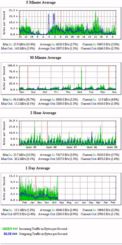
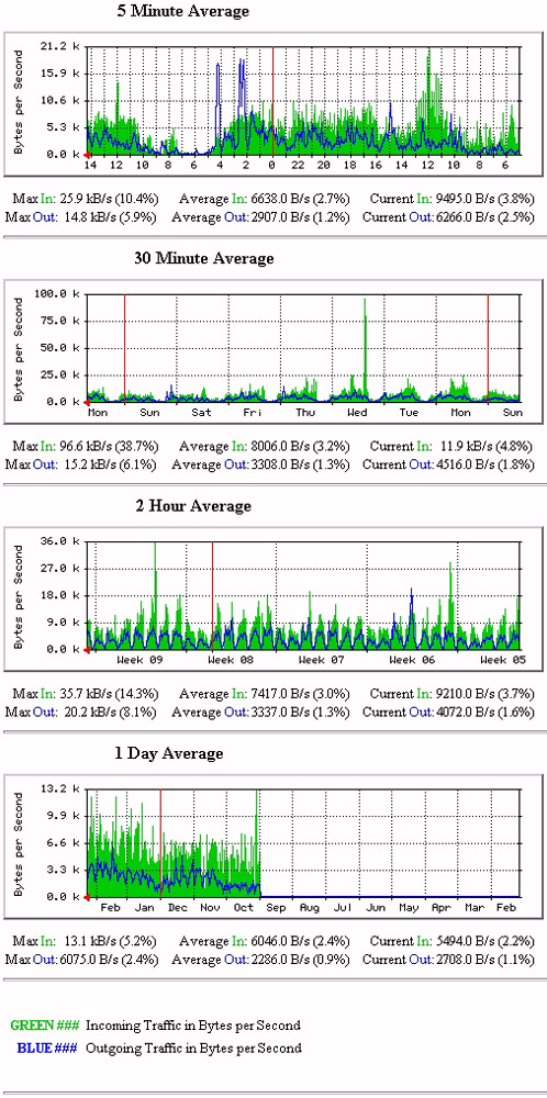
The number of pages you can view will depend on the available network interfaces. Figure 4-9-4 shows a sample main graph for a router:
Figure 4-9-5 shows graphs of network traffic that have information gathered over a period of time. In it, green and blue indicate the incoming and outgoing traffic.
| Note | It is assumed that the default Apache Web Server is installed with Linux. |
MRTG Configuration
To customize the MRTG environment, change the mrtg.cfg file. Tools, such as cfgMaker and indexMaker, are available with MRTG to change the configuration file.
CfgMaker Usage
Every MRTG call requires a config file. The cfgmaker tool generates a default configuration to measure network throughput on interfaces. The command needed to run cfgmaker is:
cfgmaker communityname@machine > mrtg.cfg
For example, to run MRTG on a local machine, use:
cfgmaker private@localhost > localhost.cfg
The cfgmaker tool generates a configuration file after making SNMP queries of the device. This file includes a lot of information, along with some HTML code that may be unnecessary. In this file, the cfgmaker shows a configuration for every interface on the machine. The loopback and down interfaces are commented out. Listing 4-9-2 shows the remaining components:
Target[localhost.3]: 3:private@localhost
MaxBytes[localhost.3]: 1250000
Title[localhost.3]: moneysink.exceptionet.com (No hostname defined for IP address): ep0
PageTop[localhost.3]:Traffic Analysis for ep0
| System: | turtledawn.blackhelicopters.org in Right here, right now. |
| Maintainer: | Me |
| Interface: | ep0 (3) |
| IP: | No hostname defined for IP address (192.168.1.100) |
| Max Speed: | 1250.0 kBytes/s (ethernetCsmacd) |
Edit the configuration file before use.
IndexMaker Usage
If you are monitoring a number of links, create an overview of the index page. To do so, use the indexmaker script. This helps create an HTML page containing hrefs or references that point to your individual traffic statistics pages.
The syntax to run the indexmaker script is:
indexmaker
MRTG Configuration File
This can be generated manually or by using cfgmaker.
Listing 4-9-3 shows the way to generate a configuration file using cfgmaker:
Target[localhost.3]: 3:private@localhost
MaxBytes[localhost.3]: 1250000
Title[localhost.3]: moneysink.exceptionet.com (No hostname defined for IP address): ep0
PageTop[localhost.3]:Traffic Analysis for ep0
| System: | turtledawn.blackhelicopters.org in Right here, right now. |
| Maintainer: | Me |
| Interface: | ep0 (3) |
| IP: | No hostname defined for IP address (192.168.1.100) |
| Max Speed: | 1250.0 kBytes/s (ethernetCsmacd) |
Before using this file, add a WorkDir directive to the config file. WorkDir specifies to MRTG where to store its logs, graphics, and HTML. To put the WorkDir under an Apache Web Server root, use:
WorkDir: /usr/local/share/apache/htdocs/mrtg
If the Web server is on the public Internet or otherwise exposed to outside parties, you may want to give the directory password protection.
The keyword, target, tells MRTG which machine to query, and which interface on that machine this configuration is for. The string inside the brackets ([]) is an arbitrary label. All files generated by MRTG have this arbitrary label as prefix. The actual name appears after the colon. If there is a change in the community name or IP address of the system, you can edit it here directly.
MaxBytes is the maximum throughput allowed through the interface. In this case, MaxBytes is a 10baseT card. The MRTG program can figure out the values for most common network types. You do not have to change this value to measure throughput.
Title and PageTop are arbitrary text. Put any HTML in these spaces; it will be displayed.
After editing, mrtg config appears as:
WorkDir: /usr/local/share/apache/htdocs/mrtg
Target[localhost.3]: 3:private@localhost
MaxBytes[localhost.3]: 1250000
Title[localhost.3]: Ethernet Interface
PageTop[localhost.3]:Traffic Analysis for Ethernet Interface
Call the Helpdesk if you have any questions
If the pages are to be viewed by management, you can add a few lines of HTML after PageTop describing how to interpret the data and what the machine does.
Any number of machines and interfaces can be listed in one configuration file, provided each target has a unique label.
Automation of MRTG
MRTG can be run manually as well as automatically. To run it manually, write the following command on the console:
/usr/local/mrtg-2.9.6/bin/mrtg /home/mrtg/mrtg.cfg
To execute it automatically after some interval, set up a crontab. Crons can be kept organized for root. Create a file, /root/crons, to place all the relevant crontabs for root.
# vi /root/crons
*/5 * * * * /usr/local/mrtg-2.9.6/bin/mrtg /home/mrtg/mrtg.cfg >/dev/null 2>&1
# crontab /root/crons
This will run MRTG every five minutes and update the graphs.
MRTG Advanced Options
The graphs generated by MRTG are embedded into Web pages placed on a Web server to help a Web client view them. The Apache Web Server is available with the latest Linux installations. You can deploy the Web pages generated by MRTG in two ways:
-
Specify the WorkDir path of your MRTG inside the Apache Web Server root directory.
For example, use: "/var/www/html/mrtg/"
This will place all the content generated by MRTG in the Apache root, which can be viewed through http.
-
Keep the WorkDir setting in any location and specify an alias name in /etc/httpd.conf that points to the WorkDir.
To do so, you need to be familiar with the configurations and settings of Apache.

